Introduction
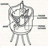
What is a Dekatron you may be asking yourself? Well, back in the good ole infancy of computing, counting (and displaying!) numbers wasn't as straightforward as it is today. Numerous technologies burgeoned through the 1950's and '60's to aid in counting numbers and processing calculations. One of these technologies was the Dekatron, or glow-transfer counting tube. The name Dekatron was a brand name used by Ericsson Telephones Limited (ETL) of Beeston in Nottingham (UK). These functioned as both counting devices and displays and came in a variety of configurations. These included counting in base 5, 10 and 12, register tubes as well as selector varieties that made dividing by n possible and hence usage in calculators and early computers. The Dekatron tube comprises a central anode encircled by a set of cathodes whereby a correct sequence of pulses can propel (or transfer) a neon (or other gas discharge) from one cathode to the next. They typically operated at pretty high voltages in the range of 450V DC. Depending on the type of gases used in the tube counting frequencies from several Hz to 1MHz were possible. Probably one of the most 'famous' examples of the use of these devices in computing was the Harwell computer.
The All-Toob Dekatron Spinner allows you to enjoy a little piece of computing history in all its warm neon glory. In homage to the days of old the spinner uses vacuum tubes as rectifiers and also a neon trigger tube (Z700U) to stay as true to the technology of the day as is feasible with cost constraints in mind! In fact this design could have been built in the 1950's as all the electronic components would have been available. This has been married to some more modern case components as the laser cut acrylic and 3D printed mounts in the case are very much of this decade. We hope you enjoy the culmination of this effort.
Manual
The manual PDF can be downloaded - see below.
Kits
I am selling a complete kit to build the spinner including the laser cut acrylic case. Details are on the shop page.

The red 3D printed parts are for illustration only... they will normally be printed in black.
As always I will sell any partial kit from a bare PCB upwards!
A Fusion 360 generated 3D image of the case is available here.
Schematic and How it works
The schematic breaks down into 3 sections:
- Power supply unit
- Relaxation oscillator
- Dekatron pulse guide driver and Dekatron
Power Supply Unit
This must provide 270V DC for the trigger tube oscillator and 475V DC for the dekatron anode.
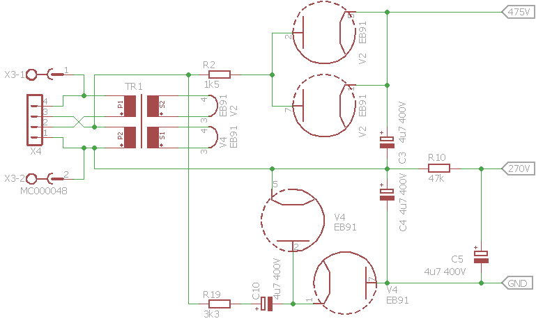
With 115V AC line/mains supply the two primaries of TR1 are in parallel. The transformer provides two isolated 6V AC supplies for the two rectifier valve heaters. The rectifiers are line/mains fed directly. V2 is arranged as a half wave rectifier produces about 162V across C3. V4 is arranged as a voltage doubler and produces about 325V across C4. These voltages are slightly lower due to voltage drop across R2 and R19. In practice about 475V is developed across C4 and C3 in series for the dekatron anode supply. R10 drops the voltage across C4 down to about 270V for the trigger tube relaxation oscillator and dekatron guide bias.
With 230V AC line/mains supply the two primaries of TR1 are in series. But the centre point of the two transformer primaries is use to feed the two rectifiers. This TR1 acts as an auto-transformer. Now fed with 115V AC the two rectifier valves operate as described above.
Safety!Note that whatever the operation the line/mains supply is rectified directly and therefore there is no isolation and the "GND" line cannot be connect to line/mains ground/earth.
Relaxation Oscillator
The trigger tube trigger-cathode gap is used as a relaxation oscillator:
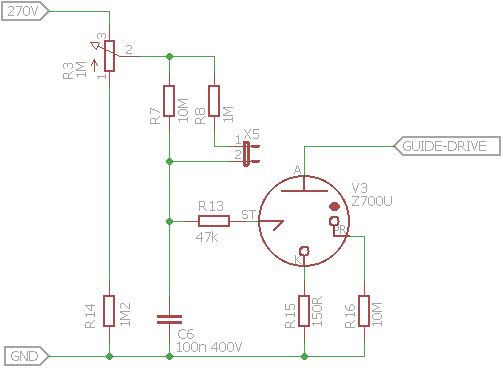
Capacitor C6 charges via R3 and R7 (and R8 in parallel if jumper X5 is fitted). When the trigger electrode-cathode gap trigger voltage is reached the gap ignites discharging C6 via R13. This is a classic neon lamp oscillator.
The function of R8 and X5 is to provide a reduction in the charging resistance path so the oscillator frequency is increased when X5 is fitted.
Potentiometer R3 provides a means to alter the oscillation frequency by a simple adjustment.
Safety!Under no circumstances should the jumper X5 be fitted or removed when the board is powered.
The shaft of R3 must be non-conductive e.g. plastic.
Dekatron Guide Pulse Driver
When you come to the complete schematic below you will see that the drive to the dekatron guide electrodes is complicated by the different arrangements required by a single pulse dekatron and a double pulse dekatron. The arrangement you choose depends on the type of dekatron you are going to spin. Both arrangements used are described by JB Dance in "Electronic Counting Circuits" and there is an extract of the book in the PDF manual. The description below is a simplified description.
Arrangement for Single Pulse Dekatrons
This arrangement is used by dekatrons such as the GC10D. This schematic shows a GC10D as an example:
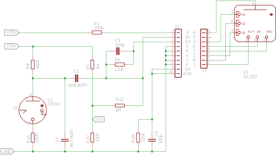
When the trigger tube V3 main anode-cathode gap is not conducting, C7 charges via R4. The final anode voltage of 270V is less than the voltage required for the anode-cathode gap to ignite until the trigger electrode-cathode ignites and then V3 conducts. C7 is rapidly discharged through V3 and R15. The voltage falls to below the maintaining voltage and the trigger tube self extinguishes.
The cycle then repeats as the trigger electrode relaxation oscillator operates as previously described.
Each ignition of the trigger tube produces a negative going pulse which is taken forward by C2. When the pulse occurs, the discharge moves one position in a clockwise direction from the glowing main cathode to the adjacent first guide which has been strongly primed by R5, R12 and R17. The anode voltage falls so that the first guide to anode potential is equal to the maintaining voltage of the tube and the discharge to the main cathode is then extinguished.
The capacitor C1 in the first guide circuit charges from the current passing to the guide and the first guide potential increases. The discharge, therefore, transfers to the second guide which is still at its maximum negative potential.
During the remainder of the input pulse the discharge rests at the second guide, but when the pulse ceases the anode potential rises so that the anode to second guide voltage is kept at the maintaining voltage of the tube. The third guide then strikes, but soon the capacitor C9 in the third guide circuit becomes charged from the third guide current to a potential which is great enough to cause the discharge to transfer to the succeeding earthed main cathode.
Finally connectors X1 and X2 allow different dekatron pinouts to be accommodated. This is fully describe in the construction section in the PDF manual.
Arrangement for Double Pulse Dekatrons
This arrangement is used by dekatrons such as the GC10B (and variants), GC10/4B, GC12/4B and their CV equivalents. This schematic shows a GC10/4B as an example:
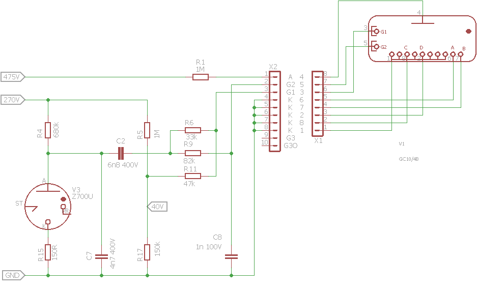
As above, when the trigger tube V3 main anode-cathode gap is not conducting, C7 charges via R4. The final anode voltage of 270V is less than the voltage required for the anode-cathode gap to ignite until the trigger electrode-cathode ignites and then V3 conducts. C7 is rapidly discharged through V3 and R15. The voltage falls to below the maintaining voltage and the trigger tube self extinguishes.
The cycle then repeats as the trigger electrode relaxation oscillator operates as previously described.
Each ignition of the trigger tube produces a negative going pulse which is taken by C2 and R6 to the dekatron first guide electrode. R9 and C8 produce a delayed negative pulse for the second guide electrode. R5, R11 and R17 provide a positive guide voltage bias of about 40V.
The arrangement describes advances the glow on the dekatron in a clockwise direction. If the connections to the guide electrodes are swapped then the dekatron glow will move in an anticlockwise direction.
Downloads

The design is open source hardware.
Note that this circuit connects directly to the mains and has potentially fatal voltages present. The capacitors will retain a charge after the circuit has been disconnected from the mains. Please take care.
You should look in the "/Dekatron Projects/Dekatron Spinner 3" folder.
Kits
The price of All-Toob spinner kits are here.
Shipping
Shipping details are here.
