Quick Links
- Introduction
- Describing the Hardware
- Clock Software
- Describing the Case Options
- Documentation
- Kits
- Customisation
- Contact Me
Introduction
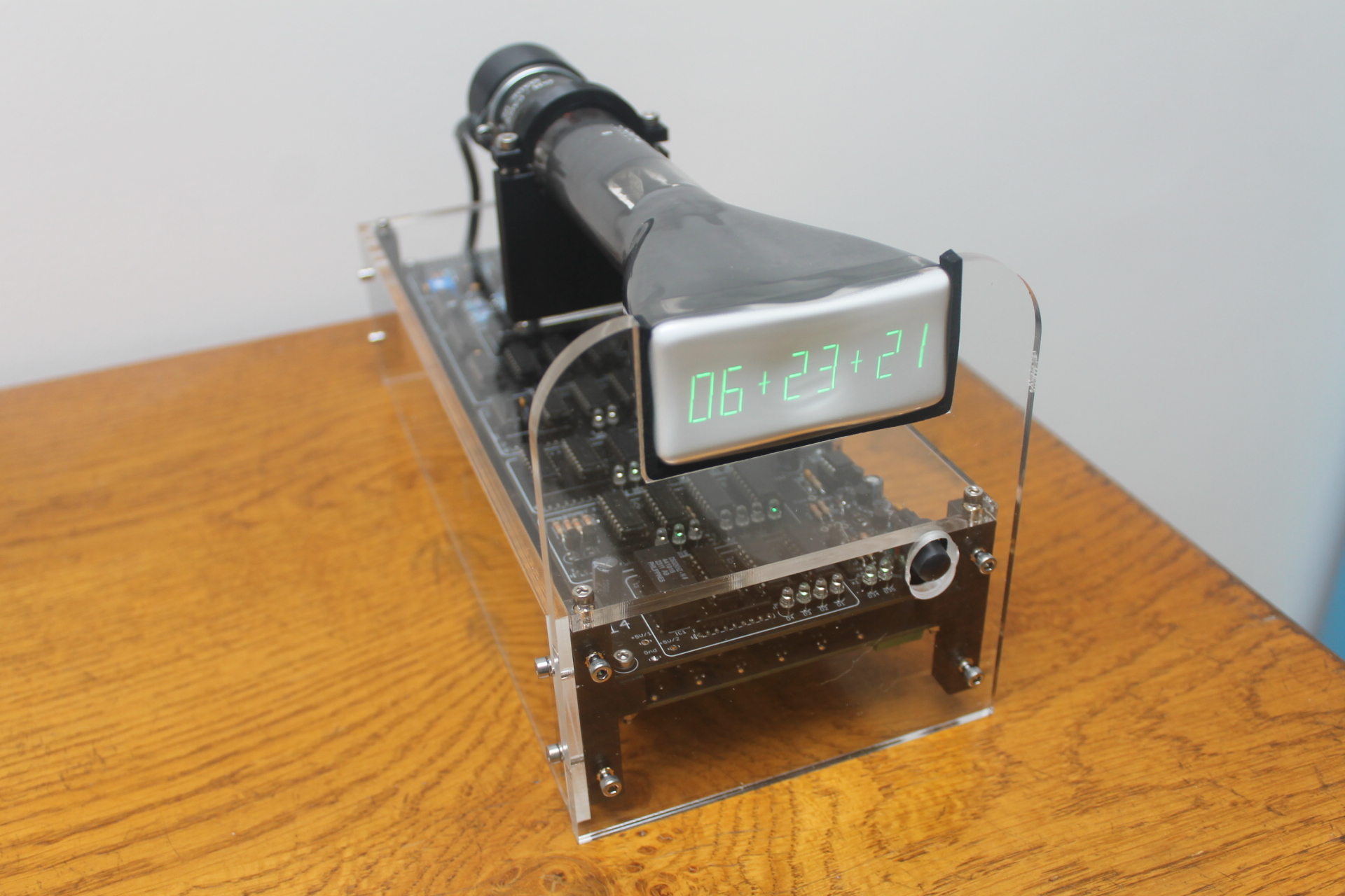
It has been a number of years since I had produced a scope clock kit so I was contemplating what the specification of a new scope clock that might become a kit… Then a friend in Sweden sent me a technical paper by AEG Telefunken from 1967. The paper's title is Ziffernanzeige auf Oszillographenröhn which Google translate told me means Numerical display on oscillograph tube. The paper and my rough translation of it are available through the documentation section below.
The Telefunken paper shows how, using a shed load of transistors, diodes and passives, a display on a CRT of 4 rows of 16 numbers could be drawn. The numbers are a simple 7 segment based characters. Clipped from the paper:
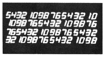
Not the best image but you get the idea hopefully!
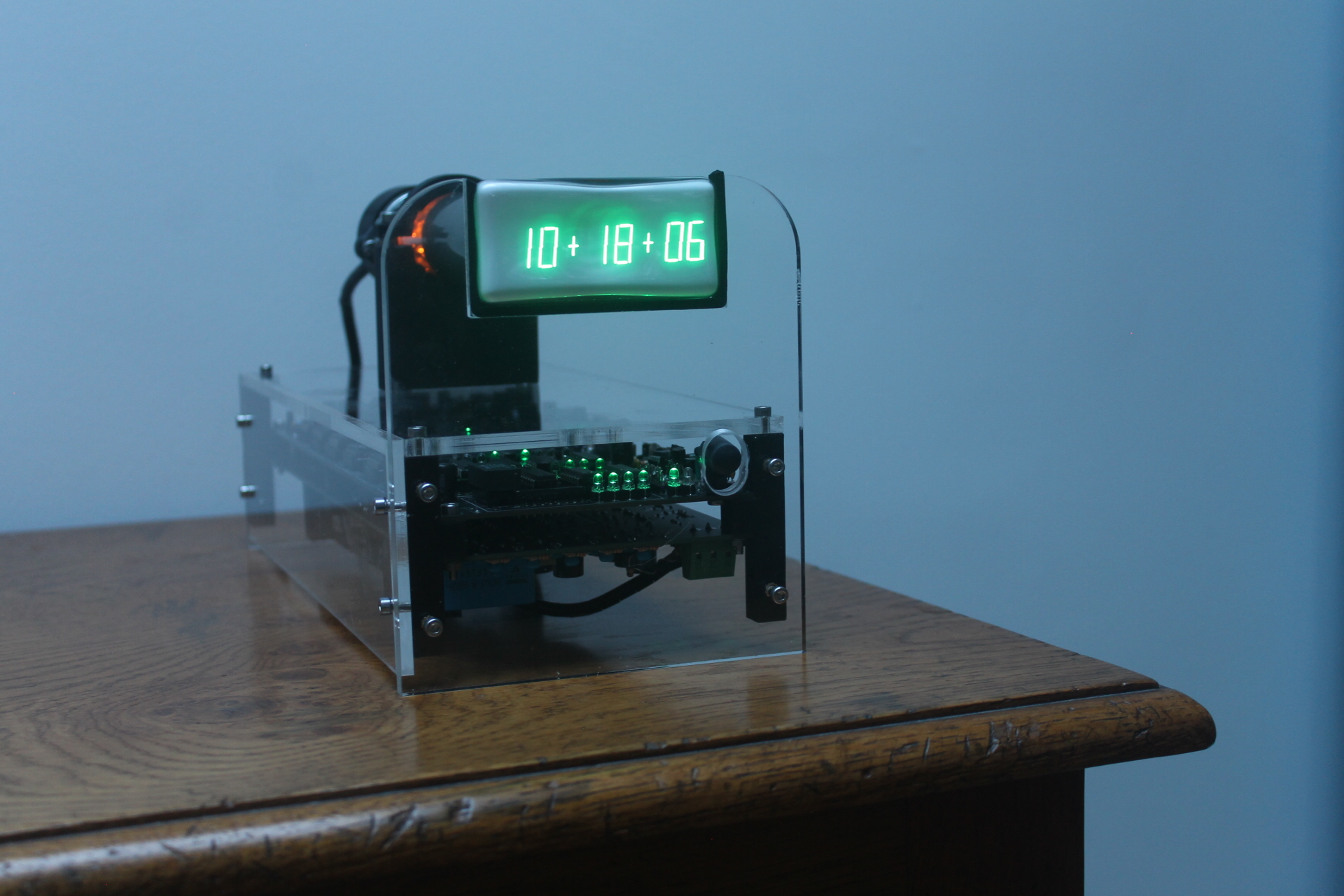
My electronics curiosity was piqued. I was (inevitably) drawn to building a clock using a simple 7 segment character display on a CRT. I would need to process just a few character for a HH:MM:SS type display. A display of 1 row of 8 characters would suffice.

Rather than use discrete semiconductors and passives, I migrated to using TTL for the time-keeping and display logic. Then use OPAMPs for the analogue processing to form the drawn characters. The CRT side of things: power supply, deflection amplifiers etc. could be derived from Scope Clock Due. I could use a simpler power supply for the CRT heater and a simpler blanking amplifier. Nick Stock suggested that I use the time-keeping from his KoolKlox and keep the BCD LED time display. This helped a lot as the point of the clock is that it is a nixie clock that uses TTL. I swapped out some of the design but the time-keeping section is basically the same.
The Scope Clock Due uses DACs to position the CRT beam at the centre of an object to be drawn and then uses a variety of waveforms: sine/cosine to draw circles and arcs, triangle wave to draw lines. Borrowing this idea, I just needed logic and some simple resistor DACs to position the beam to each line location and a triangle wave to draw a line through that point. Which lines to drawn would be decided by decoding the time into characters and then only drawing the lines needed to make that character appear.
 Quick Links
Clock Hardware
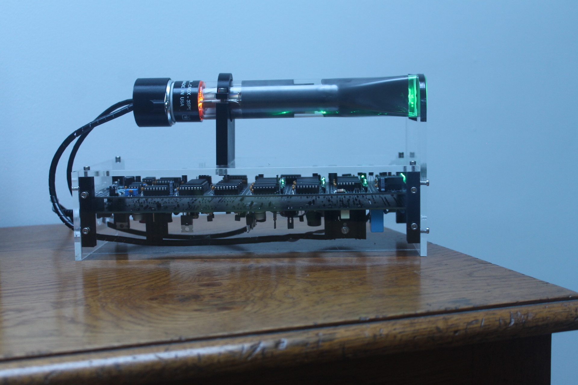
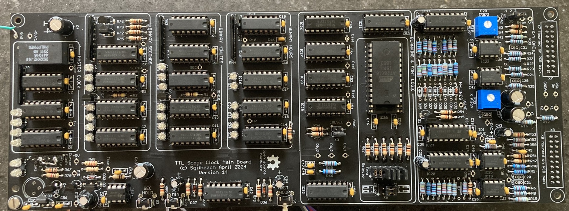
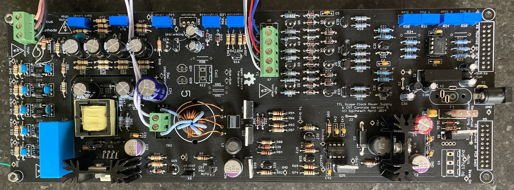
The clock electronic parts are all through-hole components - not one surface mount device was used! The clock is built on two PCBs each measuring 100mm x 280mm. The two boards are designed to be mounted back-to-back with headers joining the two boards. The board dimensions were set by the logic and analogue board and then copied for the power supply and CRT driver board. It makes the latter slightly generous in size but mechanically it works well.
Digital and Analogue Board
Power Supplies and CRT Driver Board
Quick Links
Clock Software
None!
It's all done with TTL and OPAMPs…
Quick LinksCase Designs
The cases were designed using Fusion 360. Both case designs are specific for the 3SP1 reference CRT and will need simple modifications for other CRTs. The Fusion 360 design, the acrylic cutting files and the 3D printed parts are available from the project Drop Box … see the documentation section next.
Horizontal Case
This is a common design for a scope clock - horizontal CRT on a stand.
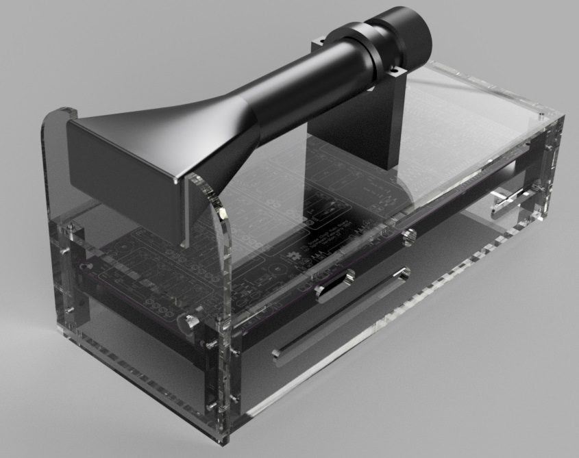
The case can be viewed here where it can be rotated exploded and manipulated.
Vertical Case
This is more unusual - a vertical CRT with a 45° mirror for viewing the CRT from the front. Not unlike a Simpson Mirroscope.
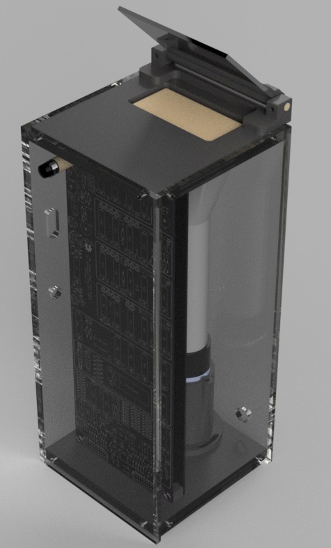
The case can be viewed here where it can be rotated exploded and manipulated.
Quick LinksDocumentation

The design is open source hardware.
You should look in the "/ Cathode Ray Projects / Scope Clock TTL" folder.
Here you will find the original Telefunken paper and my rough translation of it, the main project manual that goes through, in substantial detail, how the clock works, how to build the two printed circuit boards, how to build each of the two case designs and how to customise the clock. Also there are several spreadsheet I used in the design: a complete parts list, a spreadsheet to calculate the DAC resistor values and one to calculate the cathode and focus resistor values for different CRTs.
Here will also find the Eagle 7.7.0 schematics and board layouts, the PCB Gerbers, the F3D files for the two case designs, the STL files for 3D printed parts and DXF files for the laser cut acrylic.
Kits
Electronics Kits
Before you order a kit you must consider your ability to build it and operate it safely. It is a relatively large kit with a considerable number of solder joints to make, each perfectly. The clock use voltages from +300V down to -1500V to operate the CRT. As a minimum you will need a reasonable quality multimeter. If the clock doesn't work then it will be almost impossible to trace faults without a reasonable quality oscilloscope. Please exhaustively and completely read the clock manual PDF from the DropBox to check that you have the skill and equipment required.
The reference design uses a 3SP1 CRT. Many different CRTs will also work. The customisation section in the clock manual (which you will read won't you?) describes how the clock can be customised for a different CRT. If the changes have already been evaluated or are are small then the kit can be delivered ready for an alternative CRT.
Case Kits
Case kits are either horizontal or vertical and are sized for the 3SP1 CRT only at this time. Each case kit contains all the 3D printed parts and all the hardware but it does not include the acrylic panels. Acrylic is quiet heavy and I want to avoid shipping it twice. On the dropbox are the acrylic cutting files for either 5mm or 6.35mm thick acrylic. You can then use an acrylic cutter nearer to you. If you are in Europe or the UK then I can recommend the company that I use.
Price?
The prices of Scope Clock TTL kits and case kits are here.
Shipping
Shipping details are here.
Quick LinksClock Customisation
At a first glace there may not seem much opportunity to customise this clock but there are some…
Case
One of the most obvious customisations is not to use one of the standard cases but to design and build your own. If you do this, then I would be delighted to see a photograph of it!
Font
An EEPROM on the digital and analogue board holds the font data. Each font uses 16 bytes of storage. Each byte holds the data for one character. A 7 segment character only needs 7 bits so the extra bit is used to define an 8th line - the fonts are more 7 + 1 segments. In this font (the default font) you will recognise the standard 7 segment characters '0' … '9'. The remaining 6 characters are selectable colon characters as pairs: the clock can be set to alternate between A and B, C and D or E and F. So immediately there are options to select a range of colons and colon display effects for each font. The eighth line is a vertical centre line uses as one of the colons.

The EEPROM holds about a dozen fonts at the moment; there is room for a lot more. Fonts can be variations on the standard 7 segments. Such that the following font which has additional lines added to character '6', '7' and '9'. My favourite.

Fonts can also be creative and count in some perhaps weird fashion. This font uses BASE 5, pental or Quinary counting. I'll let you work out what each character counts. (Hint: the eighth vertical centre line has a value of quinary 10.)

Resources on the project DropBox will help edit and develop new fonts (you need to add imagination). A simple EEPROM programmer (PCB only) is also available to edit the EEPROM contents.
12 or 24 Hour Operation
Single jumper sets the hour counting mode:
- 12 hour mode - hours count '01' … '12'
- 24 hour mode - hours count '00' … '23'
Line Positioning
The position of the lines that make up each character and the position of each character are define by precision switched resistor DACs and a few diodes. These components can be changed to reposition the lines on the display. You can change the slope of each character, put additional space between characters and so on.
Resources on the project DropBox will help calculate new resistor values.
CRT Selection
Another large change you can make is the selectin of the CRT. The reference CRT is a 3SP1. By reference, I mean that this CRT that was used to develop the hardware, the standard clock kit uses this tube as does both the standard case designs. Other CRTs are almost certainly going to need changes to the electronics hardware (mostly the CRT power supply) and the case design.
The power supply and CRT board sets some basic limitations of the specification of a suitable CRT:
- electrostatic deflection and focus
- 6.3V 600mA (or less) heater
- 1.5kV acceleration voltage
- -100V blanking voltage
- symmeterical deflection
- X and Y sensitivies such that 250V will deflect the spot to the tube edge
- No PDA
Whilst described as limitations they are not all entirely absolute. For example a CRT with a 4V heater could be used but the heater transformer would need to be modified. A tube with asymmetrical deflection could work but the results would probably be disappointing.
So called "Low voltage" CRTs such as the DG7-32 are not suitable as they operate with acceleration voltage of <1kV.
Because the eight 7 segment character display it is most likely that a rectangular tube will look the best. But there is no reason why a circular CRT should not be used other than the aesthetic appearance of the clock. CRTs with a high X/Y ratio look particularly good, for example a 3ASP1:
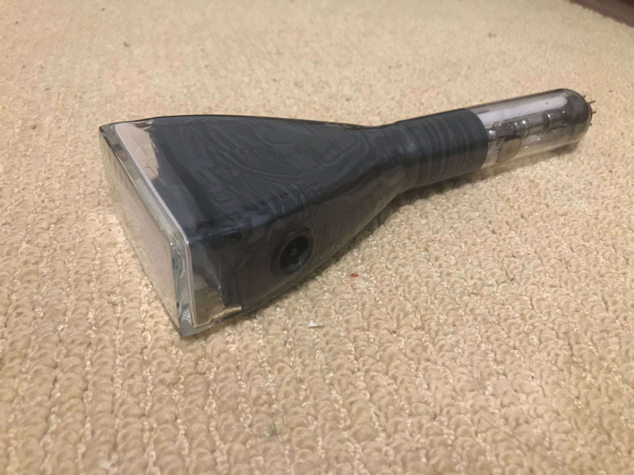
The 3SP1 and 3ASP1 CRTs are examples of rectangular displays with a high X/Y ratio. Other rectangular CRTs that have been identified as likely candidates are (this is not an exhaustive list):
-
50mm tubes:
- D6-100GH
- 75mm tubes
- 100mm tubes
- 160mm tubes (monsters)
Rectangular tubes that are unlikely to work include 4MP1, 4NP1, 4QP1, 4VP1, D10-19 - too high voltage requirement, have a PDA, are insensitive etc.
The phosphor colour and glow persistence must be considered when selecting a CRT. Unlike the display on many scope clocks, this clock is not very dynamic with lots of moving lines. It is unlikely that a long-persistence phosphor such as P2 or P7 will produce results more interesting than a common medium (P1, P31) phosphor. It is not these phosphors won't work but the results will be perhaps disappointing. The short blue P11 phosphor is a very nice colour but tends to produce a dim image.
Frank, Åke, thank you for all the tube data!
Quick LinksContact
Please contact me with any questions or enquires about ordering or postage.
