

Photo Gallery
See also Stock's Clocks
Introduction
What is The Harwell Dekatron Clock? It's the culmination of two like-minded individuals who like to tinker with vintage display technologies and turn them into functional time-pieces. This clock is unique in many respects. The Harwell Dekatron Clock is a combination of old-skool technology married with a very modern micro-controller and 21st century case construction and aesthetics. It offers lots of customisation options, such as different "faces", LED colours (bling), chimes, GPS or WIFI disciplined timekeeping and is also open source in its design philosophy.
What is a dekatron tube?

The plethora of methods developed during the late 1940's to the 1970's for displaying/counting numerical information were numerous and varied. These included incandescent displays (e.g. edge lit displays such as those from Non-Linear Systems), neon gas based displays such as Nixie tubes and vacuum fluorescent displays (VFDs), E1T tubes, light-emitting diodes (LEDs) and liquid crystal displays (LCDs). Some of these possess a certain charm, such as nixie tubes and dekatrons with their warm orange glow and others not so much.The dekatron (or generically three-phase gas counting tube or glow-transfer counting tube or cold cathode tube) is a gas-filled decade counting tube. Dekatrons were used in computers, calculators and other counting-related products during the 1950s and 1960s. "Dekatron," now a generic trademark, was the brand name used by Ericsson Telephones Limited (ETL), of Beeston, Nottingham (not to be confused with the Swedish TelefonAB Ericsson of Stockholm). The dekatron was useful for computing, calculating and frequency-dividing purposes because one complete revolution of the neon dot in a dekatron means 10 pulses on the guide electrode(s), and a signal can be derived from one of the ten cathodes in a dekatron to send a pulse, possibly for another counting stage. There are also 8 cathode and 12 cathode designs as well (also referred to as dekatrons).

A far more detailed explanation of how to electrically drive a dekatron can be found in the project documents. There are also some great resources on the web for history and data about dekatrons.

Although this webpage almost exclusively talks about using British dekatron tubes, there should be no reason why the design should not adapt to use Soviet or American tubes (it is our intention to make such changes).

Quick Links
- Introduction
- Describing the Hardware
- Suitable Dekatrons
- Describing the Case Options
- Describing the Software
- Open Design
- Documentation
- Built Clocks
- Clock Kits
- Contact Me
- Further Reading
- Acknowledgements and other dekatron devices including clocks
Describing the Hardware
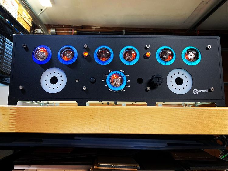
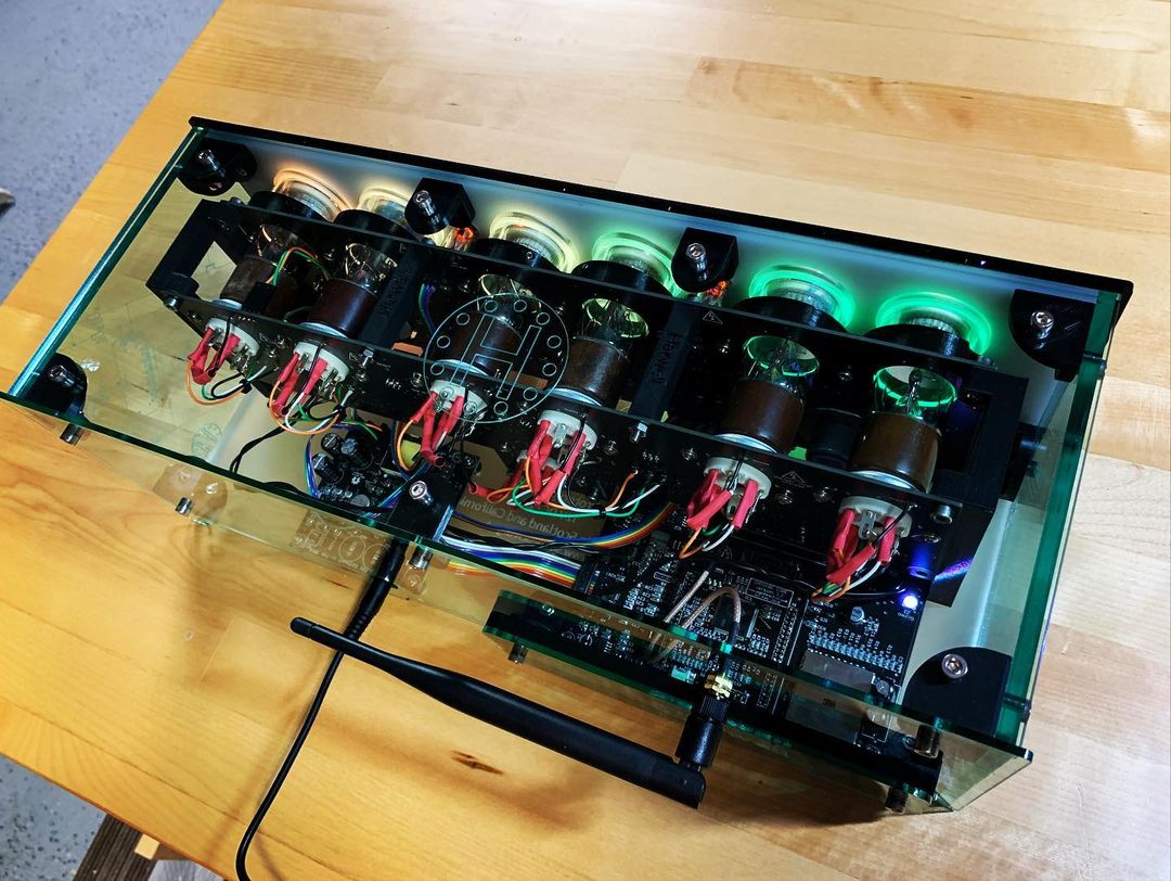
The clock hardware is complex and we think comprehensive. We wanted to respect the rarity of these tubes by creating a first class clock to use them. The main elements of the hardware are:
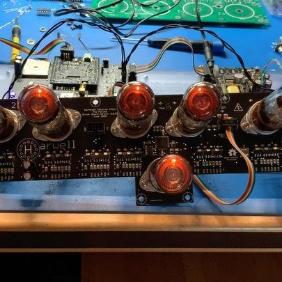
- Seven dekatron tubes with drivers to pulse and detect when the '0' cathode is lit.
- A 170V and 500V power supply for the dekatron tube guide electrodes and anodes. This power supply is switched on/off by the microcontroller so it can be turned off when not required *. Secondary regulators fed from the 170V supply produce the intermediate voltages required by the dekatron drivers such as 50V and 100V.
- A 5V 2A power supply with a voltage supervisor chip
- A 3.3V 1A power supply
- A super cap to provide back up power
- An external 12V DC 2A power supply for the clock
-
A plug in microcontroller unit that uses a SAM3X8C microcontroller (this is a smaller brother of the SAM3X8E
used on the Arduino Due but unlike the Arduino, the implementation is not neutered). The plug in board carries:
- its own 3.3V regulator
- a 32.768kHz temperature compensated crystal oscillator for time keeping
- a USB interface that is used to make the SD card (see below) appear as a removable disc drive
- a serial interface for programming the SAM3X8C and to act as a simple serial console
- A high speed native SD card (not using the SPI) which can be used at a 50MHz clock speed and has a 4 bit interface with the microcontroller. The SD card is used to store all the configuration data for the clock. Most configuration data is stored in simple text files (INI or CSV) so they can be edited by the clock owner. The SD card also stores the audio files (WAV) that are used to play the clock's chimes (see below)
- A small amount of non-volatile memory to store clock internal data without needing to write to the SD card
- Eight user selectable jumpers to hardware select operating options that can override any software settings
- Stereo audio amplifiers used to play sounds for chimes, warning beeps etc.
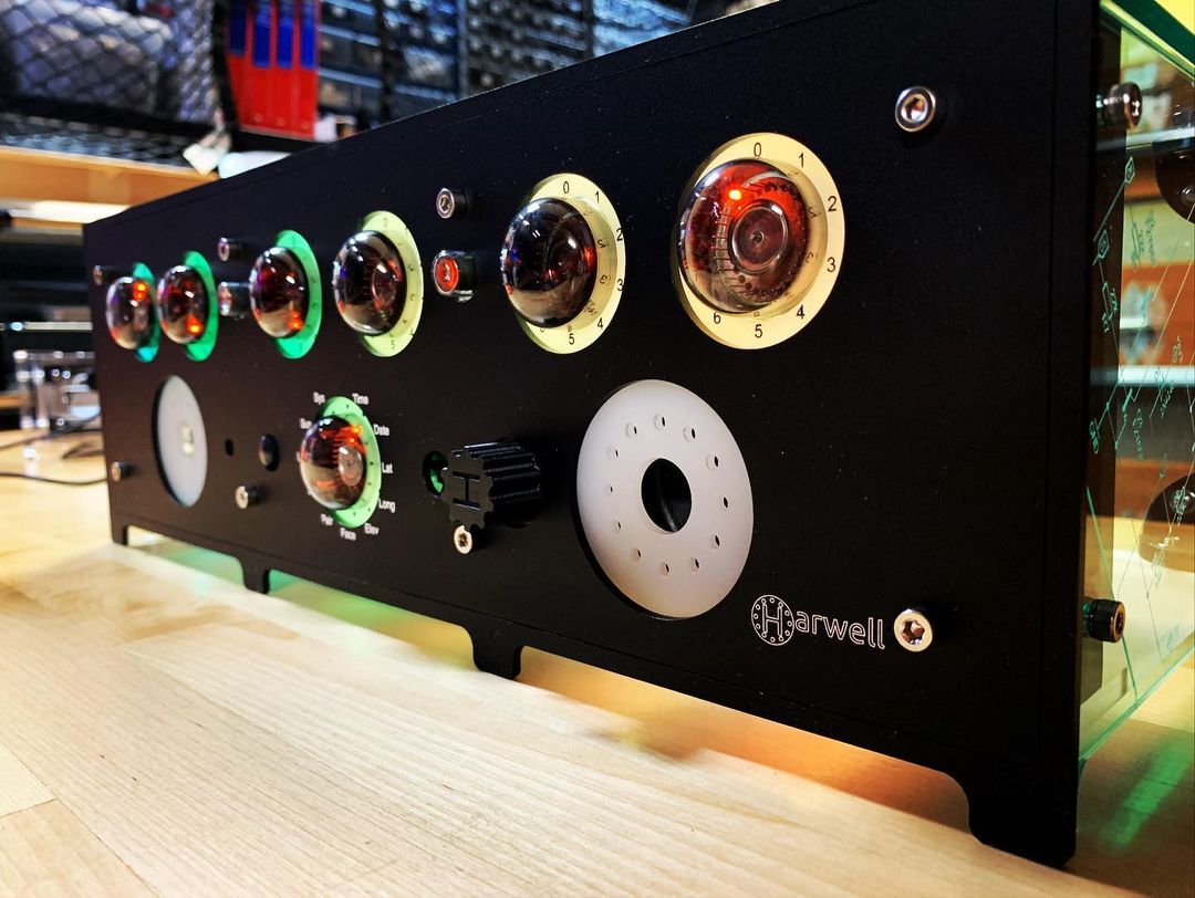
- A rotary encoder to select the clock "face" to display (date, time etc.) and to adjust the chime sound volume
- An infrared receiver and remote handset to provide more comprehensive control than the rotary encoder provides
- A PIR sensor to detect room occupancy. If the PIR does not "see" anyone for a period of time then the high voltage power supply can be shut down - the clock goes to sleep *
- An optional plug in module that can carry:
- An ESP32-BIT WIFI module to use a local network to acquire the date and time. There is the potential here to fetch other information from the internet. The Bluetooth interface is currently unused
- A GPS module to acquire the data and time. The number of satellites in view and in use is also available
- A simple serial interface (in development) to acquire data from other external gizmos
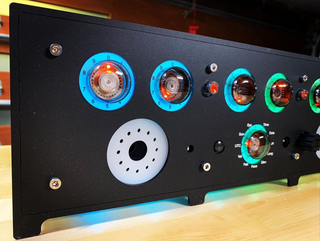
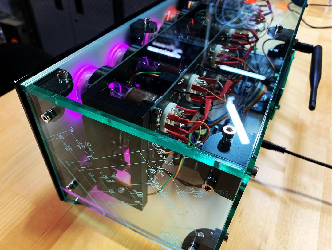
- A lot … I repeat … a lot of LED tri colour modules to bling-bling the clock. Modules are used to illuminate acrylic light guides around each tube and a few also point downwards to illuminate the clock's base. Four further modules are used to light acrylic light guide near the chime speakers
- Two MTX90 thyratons to act as colons. These are fed with PWM pulses so their brightness can be changed
- Any unused microcontroller I/O pins, the TWI bus and the SPI bus (3 channels unused) are brought out to optional connectors to facilitate expansion
- An external programmer and serial console box. This has a USB interface to your PC. It is used to program the SAM3X8C and the ESP32-BIT (if used), and acts as a serial interface using a simple menu command system.
The items marked * above are primarily intended to prolong the life of the dekatron tubes although they may have secondary benefits such as reducing power consumption.
Quick LinksSuitable Dekatrons
The case and boards place constraints on the dekatrons that can be used:
Suitable dekatron arrangements are:
- British GC10B (and variants) for the top row of six dekatrons and a GC12/4B (CV5243) for the single bottom dekatron (preferred arangement)
- British GC10B (and variants) for all seven stations
- American 6802 (or CK6802) for all seven stations
GC10B variants include GC10B/S, GC10B/L, GC10/4B, GC10/4B/L, CV1739, CV2271, CV2321, CV6044, CV6100, Z302C, Z303C, VX9194, VX9194/4B, M2465-401C.
There are variations to both the electronics kit and the case kit (espically changes to the engraving) depending on the arrangment to be used. So it is important that the choosen arrangement is stated when ordering either kit.
Dekatrons that are NOT suitable are:
- Any dekatron that does not have an octal base (this rules out register and selector tubes)
- Other British octal dekatrons, such as, GC10A, GC10C and GC10D
- Any Soviet tube, including the ОГ4 (OG4)
If in doubt ask!
Quick LinksDescribing the Case and Cover Options
Build your own
The simplest case option is to craft your own design. The physical size and board layouts will limit what you can do. But the choice of materials is entirely your own.
Safety: If you have a metal case or exposed metal parts then you must electrically bond the metal to the clock's negative supply. There is a screw connector on the PSU board for this purpose.
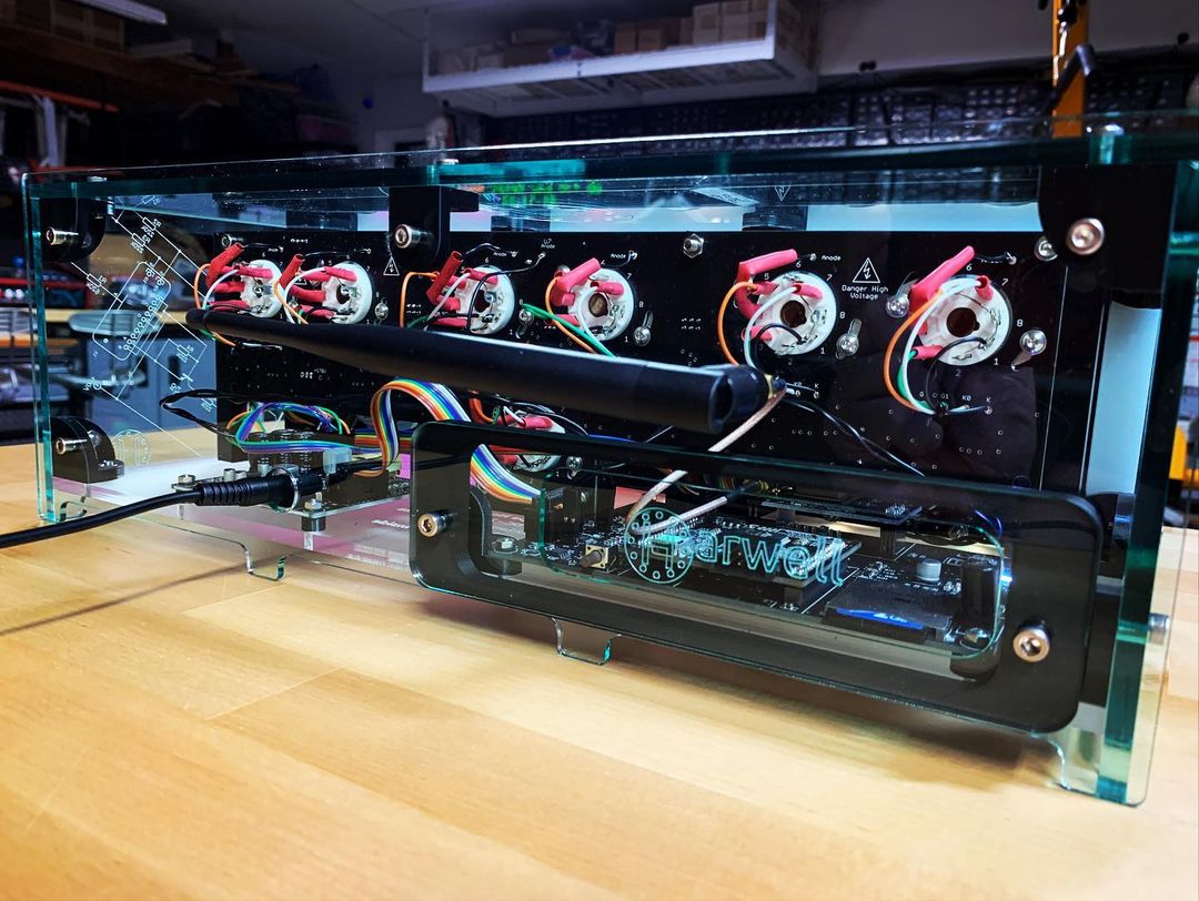
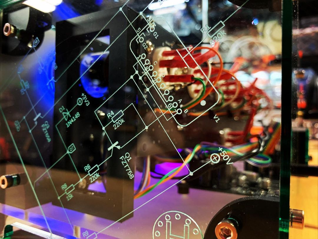
Acrylic Light Guides and Case
- 3.2mm and 6.35mm laser cut "glass look" acrylic case
- Light guides and laser cut acrylic light dispersal parts
- Engraving
- Supplied from the San Diego, USA
Describing the Software
For the SAM3X8C
This is written in C using Atmel Studio 7 and the GCC ARM compiler. It makes extensive use of the Atmel libraries.
The source code is open. You can download the complete source code from the project dropbox together with compiled binary file. The binary is burned into the SAM3X8C using the external programmer and BOSSA flash programming utility.
Instructions for burning the SAM3X8C using the external programmer and, should you wish, compiling the source code are in the project documentation.
For the MEGA324PA (on the dekatron board)
This is written in C using Atmel Studio 7 and the GCC AVR compiler. It is open source and uses the Atmel libraries.
The source code is open. You can download the complete source code from the project dropbox together with compiled binary file.
Instructions for burning the MEGA324PA and, should you wish, compiling the source code are in the project documentation. The MEGA324PA will normally be delivered burned with the latest firmware. The MEGA324PA contains both the operating software to drive the dekatrons but also contains a bootloader so the chip can be updated by the SAM3X8C using the TWI.
For the ESP32-BIN (if used)
The ESP32-BIN module uses compiled binaries from the ESPRESSIF website.
Instructions for burning the ESP32-BIN using the external programmer are in the project documentation.
For the MEGA16U2 (on the external programmer)
This is written in C using Atmel Studio 7 and the GCC AVR compiler. It is open source. It uses the Atmel and LUFA libraries.
The source code is open. You can download the complete source code from the project dropbox together with compiled binary file. The binary is burned into the SAM3X8C using the external programmer and BOSSA flash programming utility. The SAM module will normally be supplied fully assembled and tested with the latest firmware burned.
Instructions for burning the MEGA16U2 and, should you wish, compiling the source code are in the project documentation. The MEGA16U2 will normally be delivered burned with the latest firmware and the programmer partially built and partially tested.
About Nuggle

Ok, you are now thinking, what's a Nuggle?
What has a mythical creature from Shetland folklore got to do with The Harwell Dekatron Clock? I will explain some of the details…
Consider what happens when the clock is running:

Happenings or Events occur such as shown on the left … such as the clock ticks, the PIR senses motion and so on. The clock software must then decide what to do. So, for example, if the clock is currently showing the time in a hh:mm:ss format and the clock ticks one second then the dekatron display will need updating, the clock colons, if flashing, will need their state changing and if a tick sound is played then that will need to be started.
In other words, given a range of Events, the clock software must Decide on what Actions to take.
The starting events are fairly few in number as seemingly are the actions to take. But when you consider that there are twenty one events for the IR handset (one for each key), there are about a dozen sleep states and six types of tick (second, minute, hour, day, month and year) the starting event list grows in size. The actions you can take for the chime sounds is to play any audio file on the SD card (so the number of audio files is only limited by the SD card capacity), the number of beeps (frequency, duration, stereo channel) is similarly a large number, there are 32 bling LED modules, each module can (in theory) display over sixteen million colours. Against these numbers the dekatron tubes are much more defined with only 30 states to consider (36 for the seventh dekatron) giving a mere 216 options.
A common course would be to write code in C that handled a number of configurations where the actions taken for each event are programmed and burned into the SAM3X8C microcontroller. There is a disadvantage to this approach - editing or creating new clock configurations requires the source code to be edited, compiled, burned and then tested. It also makes the distribution of any new configuration more difficult. Therefore a different approach has been taken - to encompass the decision making process in a simple text script on the SD card. Here's an example:
The script "language" is a mixture of Pascal and C, and, for reasons that I'm going to leave obscure, I called it Nuggle. The text files on the SD card have a .NUG extension.
The example above does no more than display the current local time on the six dekatron tubes and to highlight the engraved "time" on the seventh. It does allow for the user time display preference (12 or 24 hour format). And it flashes the colons each second. But it makes no use of the other light guides, no use of the chimes and it certainly does not beep.
The Nuggle language manual is available from the the project dropbox. Nuggle has a Harwell Dekatron Clock supplement covering the Nuggle commands that are unique to this clock. The intention is that Nuggle will be extended to work with future Sgitheach clocks. You will find it used in the Fortress E1T Clock and it is likely to feature in future clocks.
Quick LinksAbout Open Source
One intent of the Harwell Dekatron Clock project from the outset was that the hardware and software would be fully open. The project documentation is held on a dropbox where you will find:
- The full schematics as images
- PCB layouts as images
- PCBs as Gerbers (used for manufacture)
- Parts lists with suggested sources
- Eagle (version 7.7.0) schematic and layout files
- All 3D printed parts as STL files (see below)
- All acrylic case laser cutting and engraving information as DXF or SVG files

- The source code of all the code written by us (there are elements from third parties that are only available as binaries) so this includes:
- Source code for the MEGA16U2 used in the clock programmer
- Source code for the MEGA324PA used in on the dekatron board (both the normally running code and the TWI bootloader)
- Source code for the SAM3X8C used in the main clock
- The source code files as provided as Atmel Studio 7 projects
- All clock "face" control files (will be on the SD Card in the clock)
- All clock data files (DST rules, Time Zones, Help files etc. on the SD card)
If I have missed anything from the list that I should be providing then rest assured that I will.
The 3D printed parts and other case components were designed in Fusion 360. Whilst the F360 files are not immediately available on the dropbox, I will provide them if asked. The reasons I don't immediately provide them is they are a bit of a faff to export from F360, that I suspect the demand for them will be low and they would represent yet something else to keep updated.
Quick LinksDocumentation
You should look in the "/Dekatron Projects/Harwell Dekatron Clock" and the "Common Stuff" folders.
Common Stuff includes:
- SAM3X8C plug in module
- SAM3X8C programmer
- GPS plug in module (both A2235H and A2200A versions)
- WIFI plug in module
- Simple DC power supplies
- Nuggle
- 3D printed parts
- WAV files
- Care of acrylic
Built Clocks
Fully built, tested and configured clocks are available from Stock's Clocks together with your choice of British or American Dekatrons.
Quick LinksClock Kits
Harwell Dekatron Clock Kits have sold out!
Built and tested clocks are still available from Stock's Clocks.
N.B. None of these kits include the dekatron tubes - they are yours to provide or can be bought separately!
The prices of all these kits and dekatron tubes are here.
Minimum Electronics Kit

This kit includes (from the top clockwise):
- Bare Front PCB
- Bare Dekatron PCB
- Bare Main PCB
- Bare PSU PCB
- Bare WiFi plug-in board, optional
- Bare GPS (two types), optional
- Bare Programmer board PCB
- Bare SAM3X8C plug-in board PCB
- Custom wound flyback transformer for the high voltage PSU
If you take this kit then I assume you know what you are doing! There are a lot of parts to collect. You need to be confident to be able to solder parts as small as 0603 and a LQFP100 part with 0.5mm lead spacing. You will need access to a 3D printer and be able to cut acrylic tubing accurately.
The photograph of the minimum kit shows 2x3 panellised GPS and WIFI plug in boards. You will receive only one …
Of course the real minimum kit is nothing at all - you take the Gerbers and get your own boards made and get the custom transformer wound yourself. The minimum kit here represents what I think is a more likely kit where I supply the bare PCBs and the flyback transformer.
Standard Electronics Kit
This kit includes:
- PSU board with all SMD parts soldered
-
All through hole components to complete the PSU board

- Main board with all SMD parts soldered
-
All through hole components to complete the main board

- Dekatron board with all SMD parts soldered
- All through hole components to complete the dekatron board

- Front board with all SMD soldered
-
All through hole components to complete the front board including an IR hand set and 3D printed parts


-
Parts to complete an external 12V 2A PSU

-
Fully built and tested SAM3X8C plug-in board

-
SAM3X8C programmer board with all SMD soldered (see note below)

-
Either the GPS plug-in board with all SMD parts soldered, or

-
the WIFI plug-in board with all SMD parts soldered except the ESP32-BIT module, or

- neither (the clock date and time must be set manually)
- All through-hole components to complete a GPS or WIFI plug-in board as appropriate
- External GPS antenna and bulkhead connector or external WIFI antenna and bulkhead connector as appropriate
The list of the standard electronics kit includes both the GPS and WIFI plug in components. You will only receive those you buy …
The SAM3X8C programmer board uses a ATMEGA16U2 microcontroller that must be programmed using a suitable AVR programmer. If you wish I will burn the mega for you for no charge.
Case Kit
The Case kit includes:

- 3.2mm and 6.35mm thick laser cut acrylic to build the cases for the clock and power supply
- 3D printed parts used to joint the acrylic together, hold the light guides etc. printed in black PLA
- All the required nuts, bolts etc. to assemble the acrylic and 3D printed parts
What if the kit you want is not listed?
In principle, I will assemble a kit containing the parts you request.
But I am very reluctant to provide a kit containing all the SMD parts loose for several reasons. It takes a considerable time to bag and label all the SMD parts; a considerable amount of waste is generated by the kit purchaser when all the bags have been emptied. Unassembled kits I will normally fully refund (other than the postage) if returned. However, I cannot easily use short lengths of SMD tapes on my pick and place machine so I can only offer a partial refund.
Partly or Fully built?
Please contact me if you want a partially or fully assembled and tested clock.
Built and tested clocks are still available from Stock's Clocks.
Shipping
The electronics kit is shipped from Scotland. Postage will be whatever I have to pay and no more. A complete kit will normally be shipped with tracking and insurance. Outside of the UK shipping will be by air. Inside the UK shipped Royal Mail "Special Delivery" is normally used. I will give you an estimate for shipping to your location based on Royal Mail prices and then the actual cost when posted.
You're welcome to come and collect the electronics kit … but I live near Drumnadrochit.
The case (with no electronics) is shipped from San Diego USA. USPS will normally be used.
Quick LinksContact
Please contact me with any questions or enquires about ordering or postage.
Quick LinksFurther Reading
Electronic Counting Circuits JB Dance 1967 Iffle Books Ltd.
Harwell Dekatron/WITCH computer
Quick Links