
Introduction
This page describes a series of cards that I built as experiments or to prototype sections of larger designs. Below are:
- AVR general purpose card for a 40 pin AVR
- 14 switches>
- 8 LEDs
- low frequency crystal
- TWI
- RS485 or
- RS232
- Speaker
- IR sensor
- TC74 TWI temperature sensor
- ADC inputs
- Three port IDE interface
- TWI IDE interface
- ENC28J60 ethernet interface
- W5100 ethernet interface (two types)
- LCD and keypad
- TWI experiments
- PFC8583 Clock/calendar
- Four PCF8574 I/O expanders
- Two AT24 eeproms
- DS1621 temperature sensor
- MAX521 DAC
- 90S2313 as a slave (this card predates the tiny2313) with:
- 8 bit port i/o
- 4 leds
- own ISP header
- SPI and other experiments
- ENC28J60 ethernet interface (as above)
- tiny2313 as a SPI slave
- SD card
- PS/2 keyboard/mouse socket
- RS232 interface
- RS485 interface
- SHT11 temperature and humidity sensor
- USB connector
- white noise random number generator (requires 15V DC supply)
- Screw connector breakout with LED indication
- 64 kbytes external sram test
Most (all) of these photos are rubbish - I need a new camera!
Download
You should look in the "/Workshop Projects/AVR Experiments" folder.
40 pin AVR general purpose card

This card supports most 40 pin DIL AVRs. It was built specifically for the ATMEGA32 but I have used it with others in the 40 pin packages. The card features are:
- 40 pin AVR
- 16 MHz crystal
- Each port (A to D) brought out to 10 pin headers
- Hardware reset chip
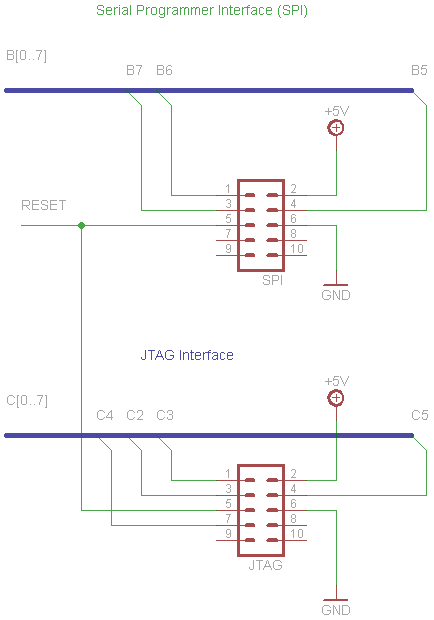
- ISP (6 pin Atmel but on a 10 pin header)
- JTAG connector
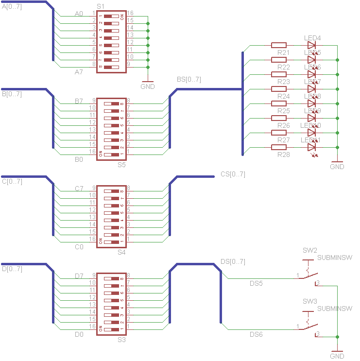
- On card experiments (switchable):
- 8 switches on PORTA>
- 8 LEDs on PORTB
- low frequency crystal, TWI and 4 switches on PORTC
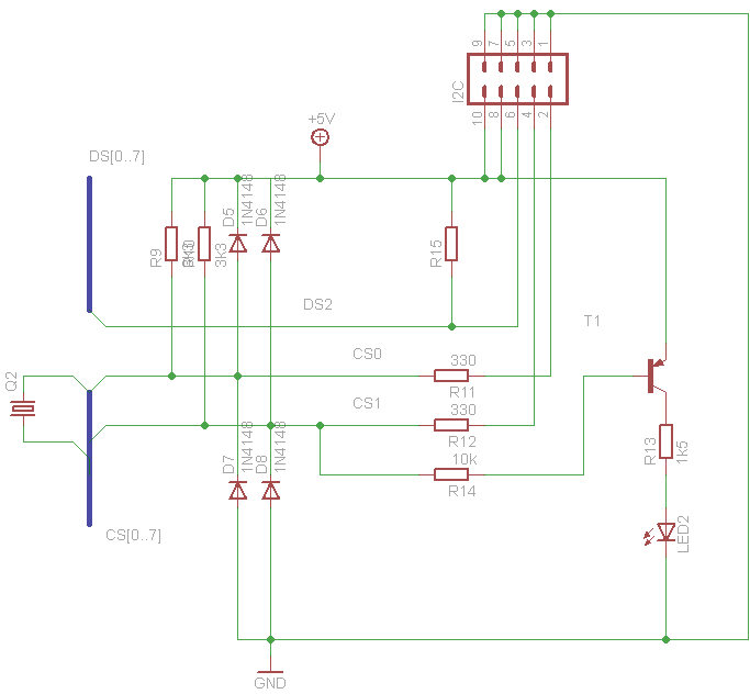
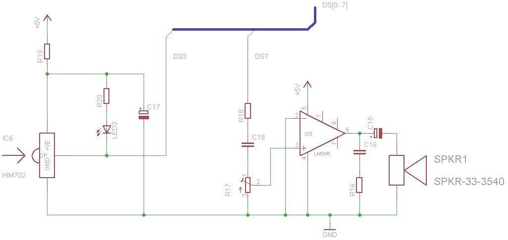
- 2 switches, RS485 or RS232, speaker, IR sensor on PORTD
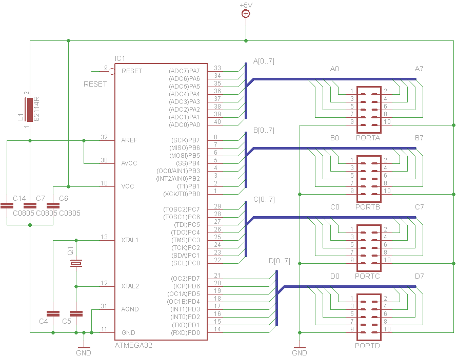
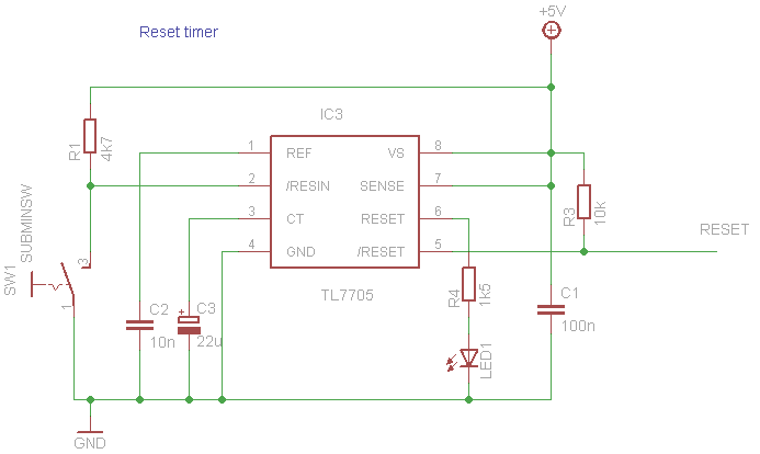
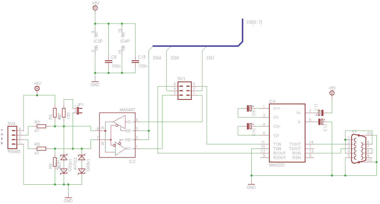
The port connectors are connected in the following fashion which is consistent across all cards:
- PORTx Bit 0
- PORTx Bit 1
- PORTx Bit 2
- PORTx Bit 3
- PORTx Bit 4
- PORTx Bit 5
- PORTx Bit 6
- PORTx Bit 7
- Ground
- +5V
The TWI connector is connected as follows, again consistent across all cards:
- Ground
- SCL
- Ground
- SDA
- Ground
- Interrupt (external 0)
- Ground
- +5V
- Ground
- +5V
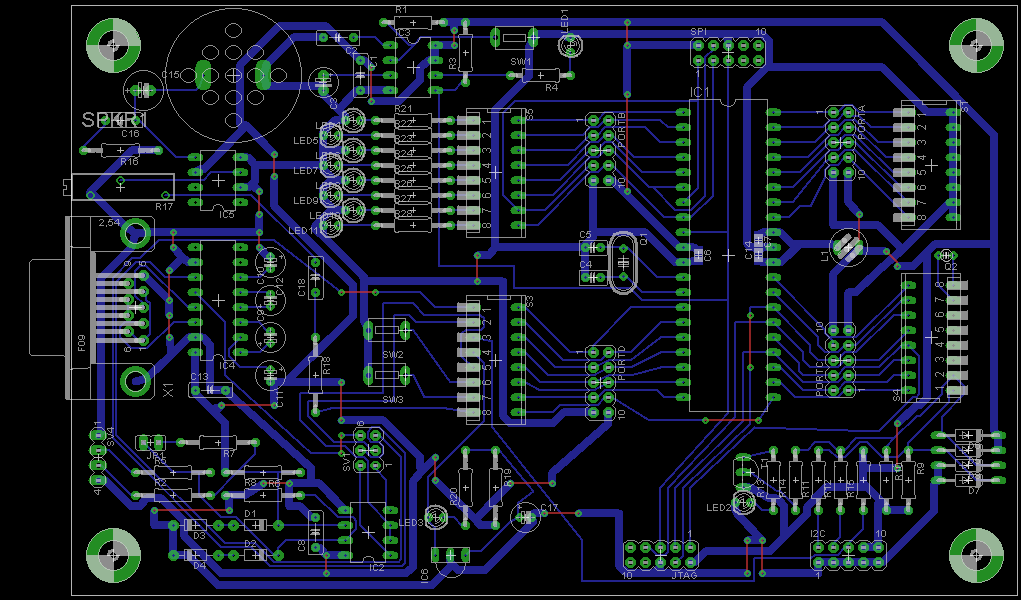
The card is single sided 100mm x 160mm PCB. The Eagle files are in the download section above.
TC74 TWI temperature sensor
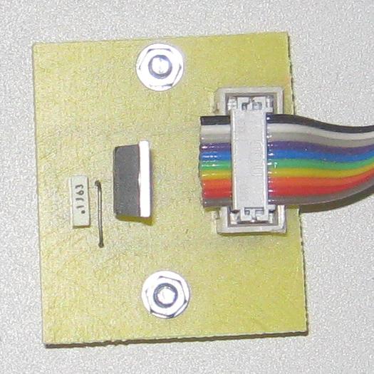
This simple card uses the TWI connector arrangement as the general purpose card and was used to test the software and prove that I knew how to talk to this sensor correctly. Just three components…


I have put this as the second example so you will see how simple some of the cards are.
Three Port IDE card

This card is used to connect a standard IDE drive to an AVR using 3 ports. Using the general purpose card I used ports A, B and C leaving port D with its serial port to communicate to a PC.


This third card again illustrates the simple nature of these experimental cards. This IDE connection enable the development of 3 port driver software which has found use in several larger projects.
TWI IDE card

The disadvantage of the three port IDE card was exactly that - it consumes three ports which on a 40 pin AVR with just four ports is rather "expensive". The idea of this experiment was to use a TWI interface to connect a second AVR with four ports to an IDE drive. But an further advantage was that the low level driver code was held in the second slave AVR which gave some space saving in the master. The project was successful, but of course, the speed was reduced compared with driving an IDE directly from the main AVR.
Here are two flavours - using a mega8535 and a mega32 (preferred):


See the TWI expansion card below which I also used to drive an IDE.
ADC Test
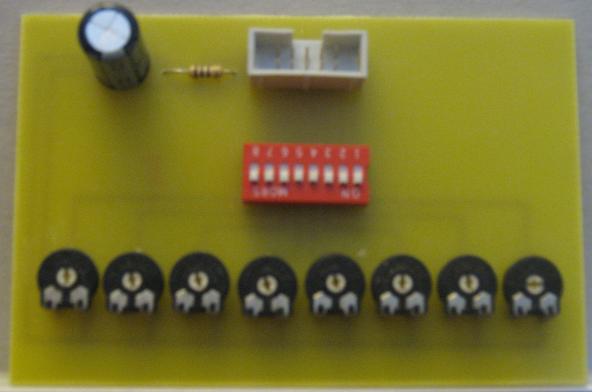
This card was used to provide dummy voltages (0-5V, 0-1023 value) to the AVR ADC inputs. Individual ouputs can be switched allowing the AVR pin to used by some other interface card.


Ok, I'll do a more complex card next.
ENC28J60 Ethernet Interface
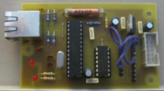
This card was built to test software for connecting an AVR to the ethernet. The board has a pair of jumpers to allow for differences in the pins used by different AVRs (e.g. ATMEG32 and ATMEGA128). The card has its own 3.3V regulator using the 5V supply and a few gates to provide voltage conversion between 5V and 3.3V signals.


This interface worked brilliantly and become the ethernet interface used in a nixie clock.
SPI W5100 Ethernet interface

The W5100 chip is a complete TCP/IP, UDP etc ethernet interface. You can buy it fro Wiznet already mounted on a carrier with some surface mount components. It has three interfaces: SPI, 8 bit data port and controls (indirect mode) and 8 bit port and full address bus (direct mode). This card was to enable the w5100 to connect to the SPI port on a mega32 (or similar). The w5100 requires a 3.3V supply so an additional regulator provides this from the 5V supply.


Indirect Port W5100 Ethernet interface

This is a repeat of the previous card except it uses one port for data (8 bits wide) and a second port for a number of control signals.


I have now used the w5100 in a number of projects - the first published on these pages is a simple NTP client.
LCD and Keypad Interface

No AVR experimental kit would be complete without a LCD to drive and a keypad to read…


TWI Experiments
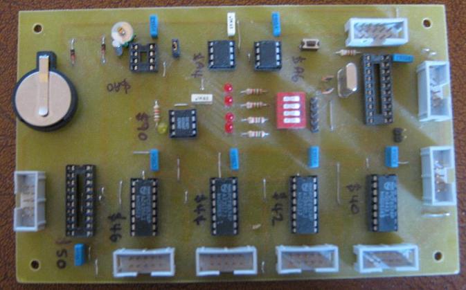
This card carries the following experiments:
- PFC8583 Clock/calendar
- Four PCF8574 I/O expanders
- Two AT24 eeproms
- DS1621 temperature sensor
- MAX521 DAC
- 90S2313 as a slave (this card predates the tiny2313) with:
- 8 bit port i/o
- 4 leds
- own ISP header


SPI & Other Experiments

The card was to carry a number of SPI and other experiments:
- ENC28J60 ethernet interface (as above)
- tiny2313 as a SPI slave
- SD card
- PS/2 keyboard/mouse socket
- RS232 interface
- RS485 interface
- SHT11 temperature and humidity sensor
- USB connector
- white noise random number generator (requires 15V DC supply)
Two 8 bit port connectors are provided and wire jumper leads are used to select which experiments are connected to which pins. The card carries a 3.3V regulator and logic to enable multiple SPI devices to be used (i.e. multiple SS signals).


LEDs and Screw Connections
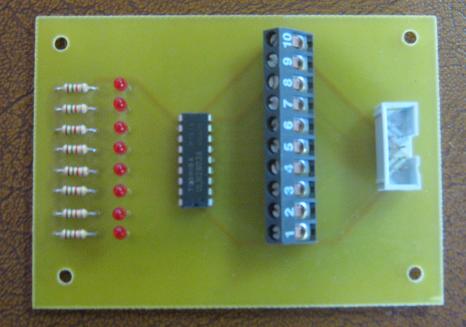
This card was to break a port out onto screw connectors and show the bit status with leds. I built two.


External Memory Test Card
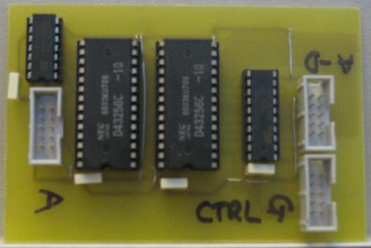
64 kbytes external SRAM - uses three ports:
- Address bits 0 - 7
- Shared address bits 8 - 15 and data bits 0 - 7
- Control bits 0 - 2 - write strobe, read strobe, ALE strobe (address line select)


This memory card is compatible with the external memory requirements of a mega128.