Introduction
I decided to build a nixie clock to sit on top of the PC in our study. My first thoughts were to control the clock (set the time, display features and so on) using the PC, probably using a RS232 serial port or maybe a USB port. An entirely separate project I have been working on is to build a bridge betwen RS485 instrument network and an ethernet network. So the thought occurred (eventually :-o) - why not give the clock an ethernet connection and plug it into the router/firewall/modem that also sits on top of the PC anyway? By this method, it could use an internet time service to self set the time when the clock was switched on, keep the clock synchronised by periodically fetching the time from a time service and have its display features controlled by the local PC via the house LAN.
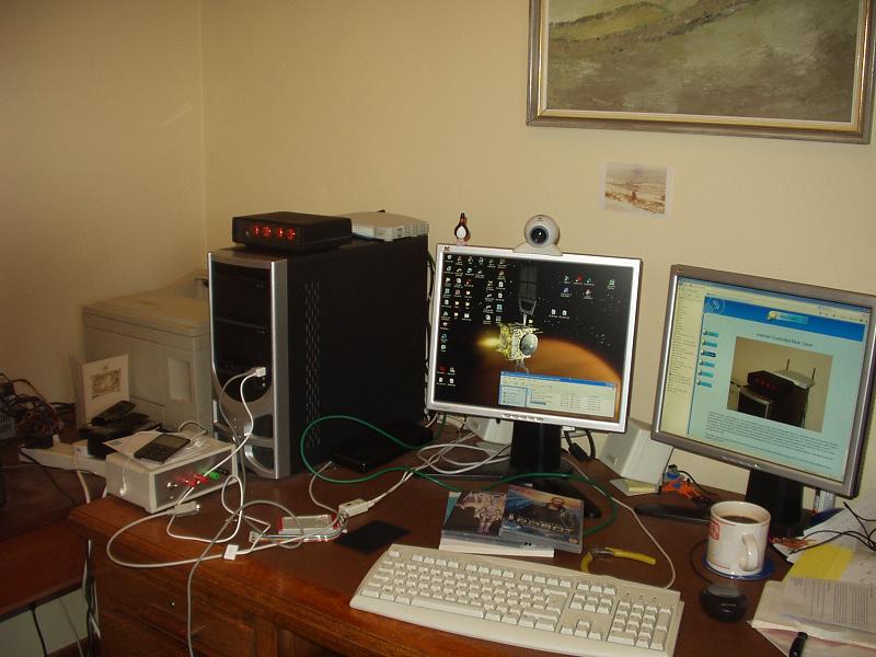
The photo above shows the finished clock (my camera is very cheap and takes crappy photos; in practice the display is much brighter
and fresher (see the last page in this series for a more general picture of my messy study).
I am now using WiFi NTP or GPS disciplined clocks so this clock has been retired.
Progress…
First came the box - this is the first clock where I have first decided what I wanted as an outward appearance; I then obtained the case before designing the rest of the clock. Previously I have rushed too fast to build the electronics before deciding how it was to be housed.
[Choosing the case the first is the way to go...]
This case measures 190 x 140 x 50 mm and made of ABS and was finally sprayed matt black. A clear acrylic window is slotted into the front, the power connector, ethernet magjack and ethernet status leds are round the back and not visible here.
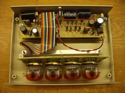
I also wanted to use the Z560M nixie, use a switched mode power supply for both the 5volt digital supply and the 180 volt anode supply for the nixies and an ATMEGA32 microcontroller to provide the "intellegence" required for the ethernet and to control the clock.
The photo above shows the case open (and before it was painted black). The three printed circuit boards are for the display, the power supply and nixie driver transistors and almost hidden underneath the driver board, the microcontroller and ethernet board.
Controller card
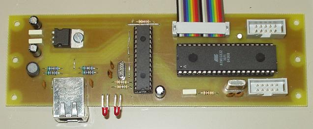
The controller card carries the ATMEGA32 microcontroller. I used this device as it contains easily enough flash memory and ram to operate the clock and the ethernet link. The ethernet link is particularly greedy for resources; without the ethernet a very much smaller device could have been used. But I had one in my spares box and at about £3 each it is not a significant cost.
The ethernet controller is an ENC28J60 from MicroChip. The ENC28J60 is a 28-pin, 10BASE-T stand alone Ethernet Controller with on board MAC & PHY, 8 Kbytes of Buffer RAM and an SPI serial interface (or it says so on the box).
The magjack and status leds are offset from the edge of the board and will eventually be available through the back of the case.
The ribbon cable connects to the driver and power supply card; one10 pin header is for the JTAG programmer/debugger and the other is Port D and is unused in this clock (although note that Port D carries the UART so I connected this to the serial port on the PC via a RS232 level shifter to assist with debugging).
Driver and PSU card
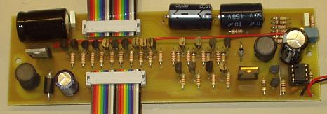
This card carries the 180v power supply, the 5 volt power supply, the 10 nixie cathode drivers and the 4 anode drivers. The nixies are driven in a 4 way multiplex mode.
Nothing on this card is really unusual, MPSA42 high voltage transistors form the cathode drivers and are fed by the microcontroller (8 bits of Port A, 2 bits from Port C). The anode drivers are MPSA42 and MPSA92 pairs (driven from 4 bits on Port B). The 180 volt power supply uses a MC34063 convertor in a standard high voltage configuration. The 180 volt power supply is split in half to produce a 90 volt supply for the display card "centre-pull" resistors used to help eliminate ghosting in the display. Finally, the 5 volt power supply uses a LM2576 in a conventional step down arrangement. (I used a switched psu rather than a conventional linear regulator to reduce heat output).
The two ribbon cables connect to the microcontroller and to the display card. The PCB layout is arranged with the controller card and driver card ribbon connectors above one another when stacked. Finally, a 12 -15 volt unregulated power supply is connected via a standard 2.1 mm power jack on the rear of the case.
Display card
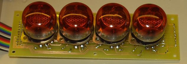
The display card carries the 4 nixies, their anode current limiting resistors and "centre-pull" resistors connectingh each anode and cathode to the 90 volt supply. The ribbon cable connects to the driver card.
Design files
You should look in the dropbox below.


Software
The code for the microcontroller is written is a Pascal/Modula 2 derivative specifc to AVR microcontrollers:
See the e-lab web site. This is an expensive compiler but I was using for work for a client who paid for it…
I admit that the software is far more complex than it need be, even takinging into account the use of an ethernet link. I wanted to fully explore the world of IP, ARP, UDP, ICMP, DNS, SNTP and DCHP. The minimum code required does not need to be as fully featured as this clock uses.
You should look in the dropbox below.
Delphi controls
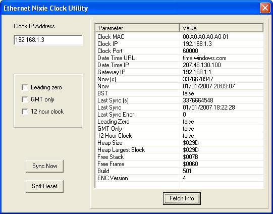
Finally, some simple code in Borland Delphi is used to talk to the clock using UDP packages.
The Clock IP address must match the address displayed by the clock as it starts up. Typically it will be 192.168.1.X on a small home network.
The clock display can be set to 12 hour mode, to force GMT and ignore BST, and to supress a leading zero in the hours display.
You can force the clock to synchronise with its time server, force the clock to restart and to fetch various data from the clock.
A future version will allow the Clock MAC, server URL and data port to be changed (the clock stores these values in eeprom so they are not lost on restart). I also planned a complete re-write into C. But didn't.
Documentation
You should look in the "/Nixie Projects/My Second Nixie Clock" folder.