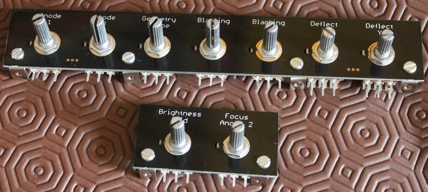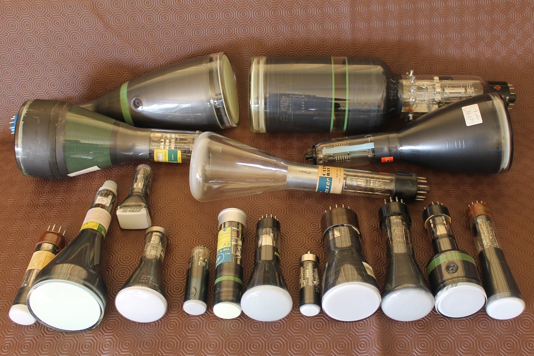
A few of my CRTs… Back row, left to right: CV5125, 5SP7 Middle row: SE5F, 6ЛO1И, 09D, 130BXB31 Front row: CV1522, D10/230, CV2175, 3ЛO1И, CV2272, DG7/32, CV2320, DG7/52A, ACR10, 7ЛO1М, 2BP1.
Ok, so you have collection of cathode ray tubes bought from dealers, ebay and friends...
Which work? Which have image problems? Which are dead? If you lack a full data sheet, how can you find out operating data such as the grid voltage for blanking? Focus anode voltage? X/Y deflection sensitivities etc.? …
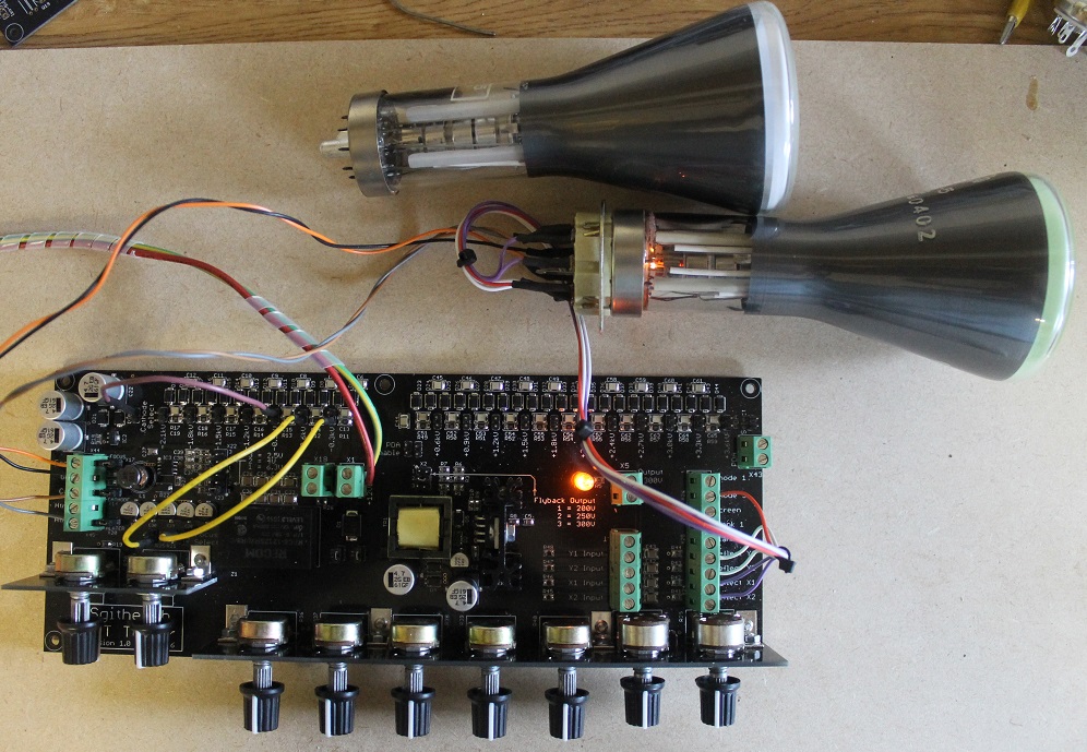
Answer 1: An Electrostatic CRT Tester
You need ones of these!
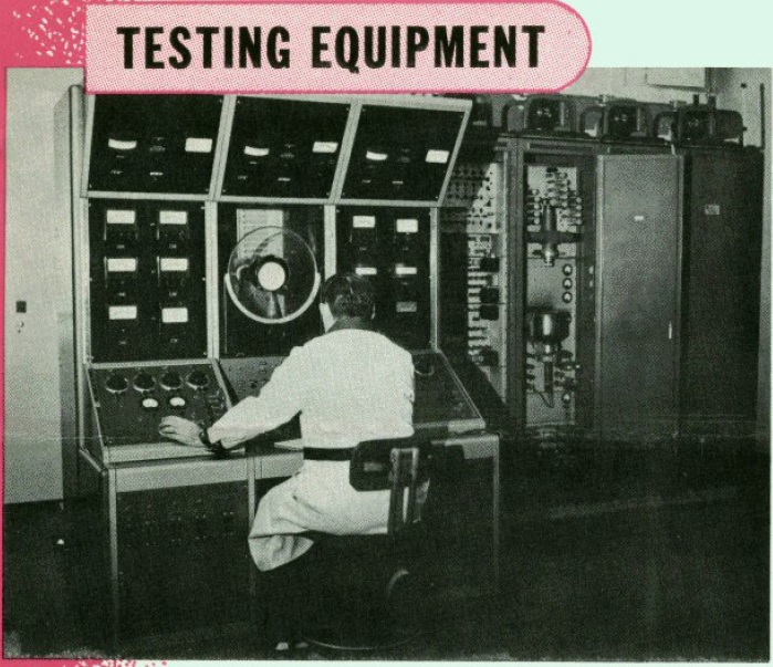
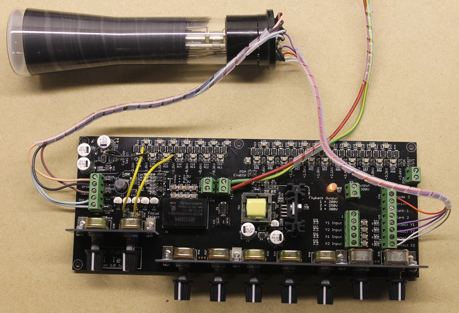
Answer 2: An Electrostatic CRT Tester
You need ones of these!
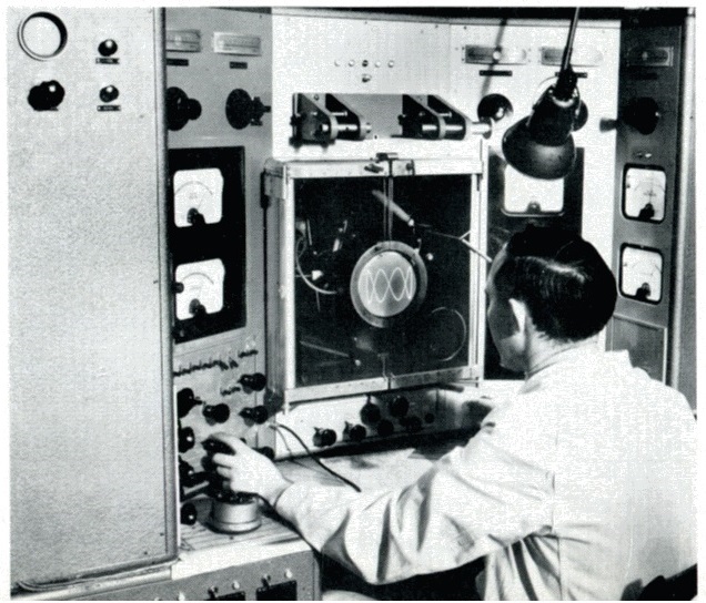
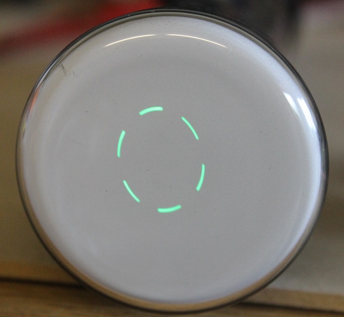
Answer 3: An Electrostatic CRT Tester
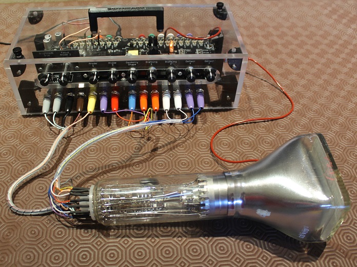
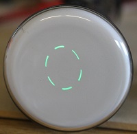
Soviet 11Л06И CRT under test
Introduction
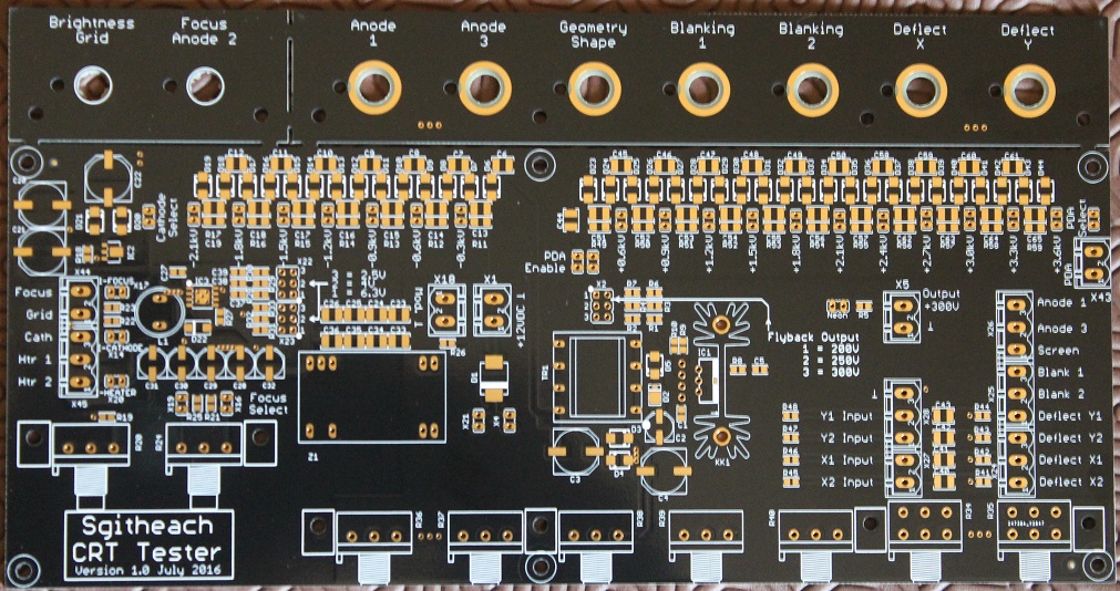
To test CRTs I used to connect together a rig made up of a couple of old Heathkit IP17 high voltage power supplies, a separate EHT power supply or I used an old scope clock power supply that wasn't very easy to adjust. I also couldn't easily test CRTs with a PDA connector. I could show that a CRT would produce a visible dot but couldn't really make measurements or operate a CRT at its correct voltages.
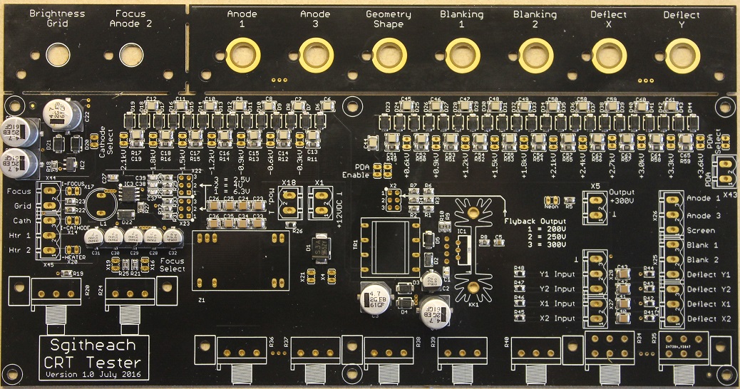
So I set about taking a scope clock power supply and putting it on its own PCB with a lot of potentiometers and jumpers to allow voltages to be finely adjust over a wide range.
This page and its documentation describes the resultant electrostatic CRT Tester. It is (almost) fully open design and open source all released under a Creative Commons ShareAlike 4.0 International license.
So you can roll your own entirely or you can buy a complete kit or or a minimal kit or a fully assembled tester - all described below or in the documentation.
Quick Links
Specification
Basic Design
- CRT heater supply limited to about 6W, say:
- 6.3V at 0.6A
- 4V at 1.1A
- 2.5V at 2A
- Grid voltage adjustable from -5V to -120V w.r.t. the cathode
- Focus anode voltage adjustable over a very wide range
- Acceleration anode voltage selectable up to about +2.2kV w.r.t. the cathode
- PDA voltage selectable up to about +5.6kV w.r.t. the cathode
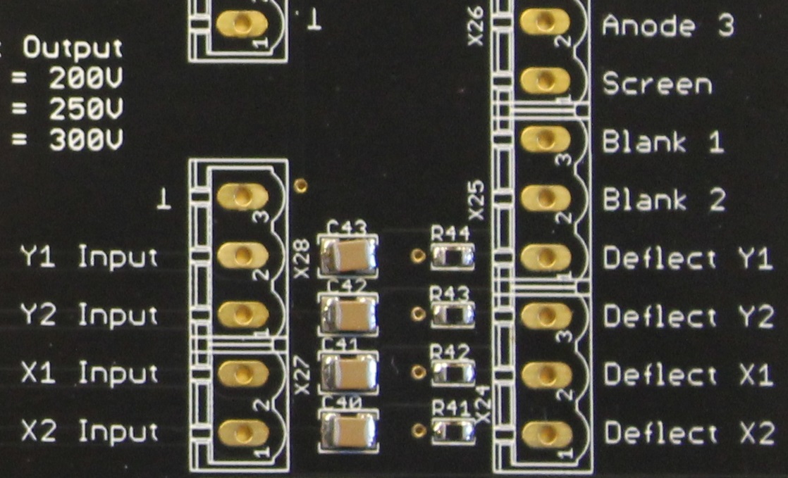
- Deflection plate voltage difference from -300V to +300V
- Adjustable deflection blanking, acceleration anode and other electrode voltages
- AC coupled inputs to the X and Y deflection plates and grid modulation (Z axis)
- Provision for current and voltage instruments
- 12V DC supply i.e. a bench PSU
Simple and manually operated - no micro-controller or PC in sight!
Limitations
There are a few limitations to the what the tester will do:
- CRT heater could not supply above 6W power, for example, 6.3V 1.2A heaters
- Multi gun CRTs could not have their guns operated simultaneously
- Electrostatic deflection and focus CRTs only (no magnetic deflection and focus)
- Trace rotation coils not tested (for non-circular CRTs)
- CRTs requiring >5kV PDA voltages but a spot should still be obtained
Some of these limitations have simple work-arounds available now or being planned.
Quick LinksGallery
Other Uses
The CRT Tester delivers a range voltages to run valve heaters, a 200V - 300V +HT supply and a wide range of EHT voltages. So it can be use to test a variety of other electronic devices. Such as
- Cold cathode neon filled devices, such as:
-
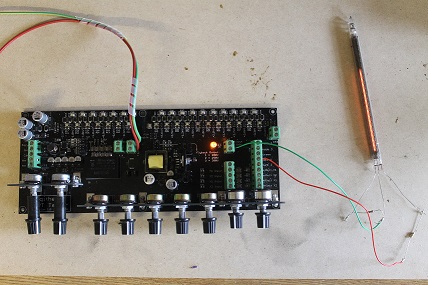
Dekatrons, here showing a GC10B under test
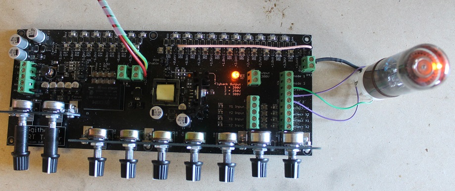
-
Nixie tubes, here showing a ZM1040 under test
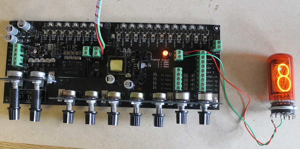
-
Trigger tubes, such as GTE175M and Z700U
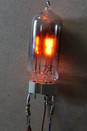
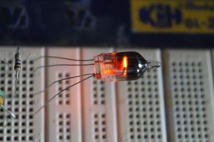
-
Bargraph indicator tubes
-
Dekatrons, here showing a GC10B under test
- Other "cathode ray" type valves, such as:
-
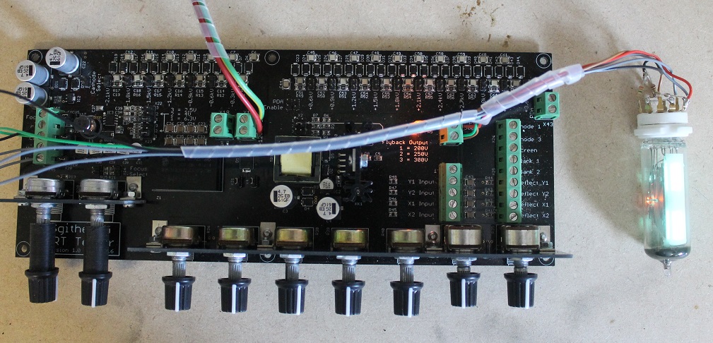
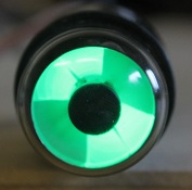
Magic Eye valves, shown here EM87 and 6AF6G
-
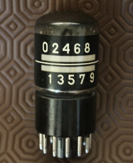
E1T valves (shown here not connected)
-
Magic Eye valves, shown here EM87 and 6AF6G
- Other gas filled devices, such as:
-
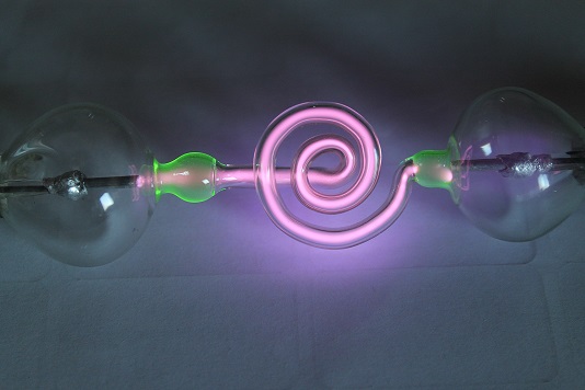
Geissler tubes
-
Geissler tubes
Case Design
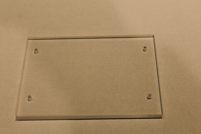
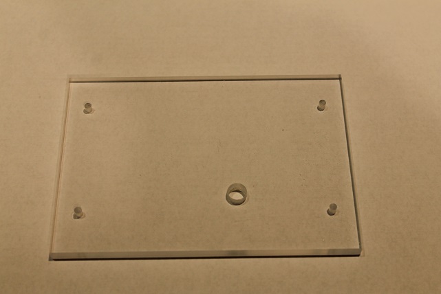
A case for the tester made from laser cut and engraved 5mm clear acrylic, together with the required fixings, banana plugs and jacks, wire and so on to house the CRT Tester is available as a kit. See the Kit Availablity and Prices section below.
(The photos of the acrylic shown here is of a prototype case without the engraved labels.)
The complete acrylic case kit comprising:
- 5mm clear acrylic - laser cut and engraved


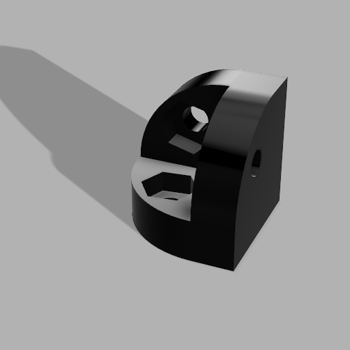
- fixings - M3 nuts, bolts, 3D printed corner fixings

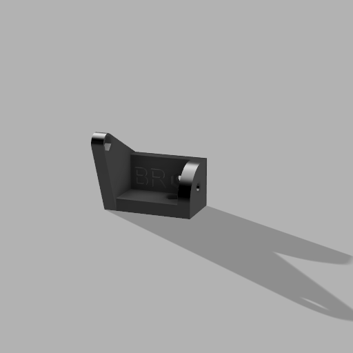

- lid corner thumb screws, 3D printed handle
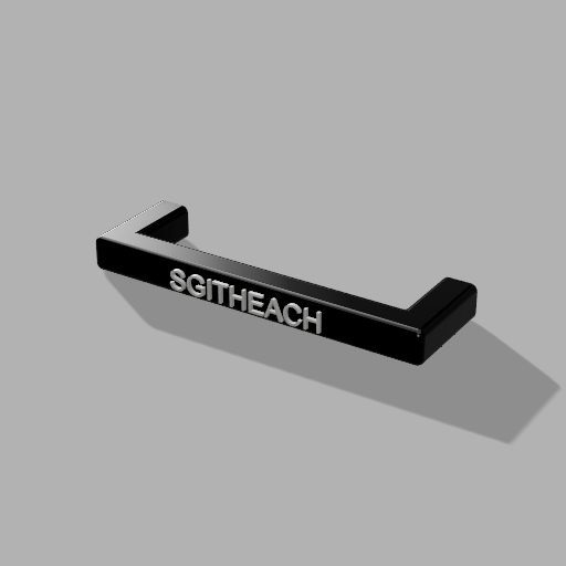
- 4mm banana jacks and plugs, connecting wire
- 2.1mm 12V DC input jack
- wire, heat shrink tubing and spiral wire wrap
Here's a part assembled case waiting to have the PCB dropped in and wired up:
 Quick Links
Documentation
You should look in the "/ CRT Projects / CRT Tester" and the "Common Stuff" folders.
Common Stuff includes:
- 3D printed parts
- Care of acrylic
Kit Availability and Prices
The prices of all these kits are here.
The electronics kit is available in two forms:
Minimum Electronics Kit
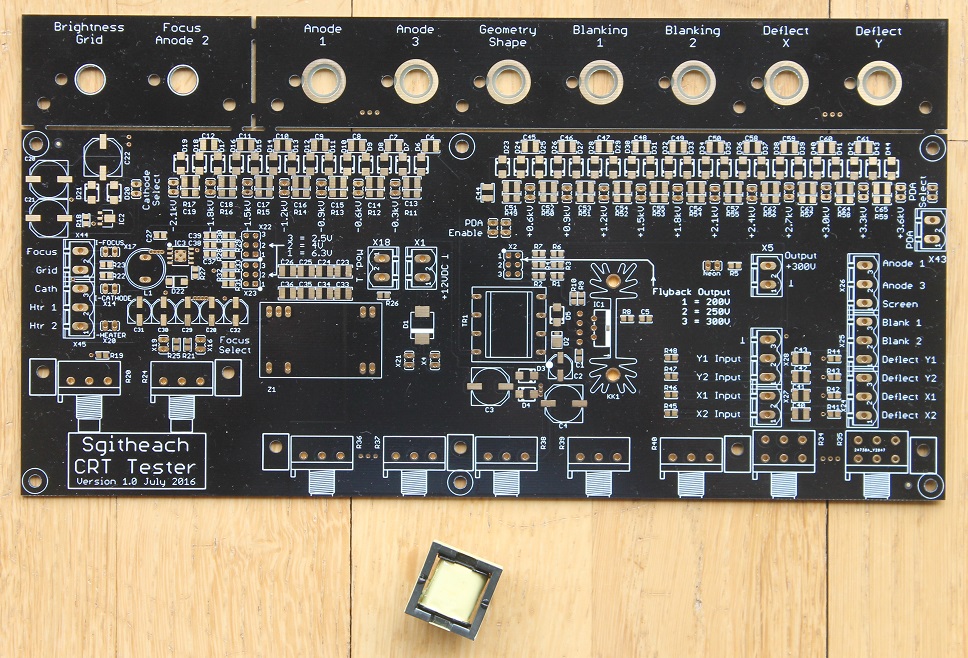
This is the PCB and flyback transformer only i.e. the two key custom made components. You will have to buy all the remaining components. I bought them from Farnell (Element14), Digikey and a few parts from Ebay. If you are going down this route the I assume you know what you are doing ….
Complete Electronics Kit

This is the PCB with all the SMD parts fitted and all the through hole components and hardware in labelled bags.
I have been asked for a kit with the SMD parts unfitted. I have found that it is far quicker to solder paste a board, pick and place all the SMD parts then pop it in a reflow (toaster) oven, than it is to pick the SMD parts and put them all in bags. It also uses less resources as I'm not printing labels and using polythene or anti-static bags. So to say the least I am reluctant to supply an SMD unfitted kit.
Complete Case Kit
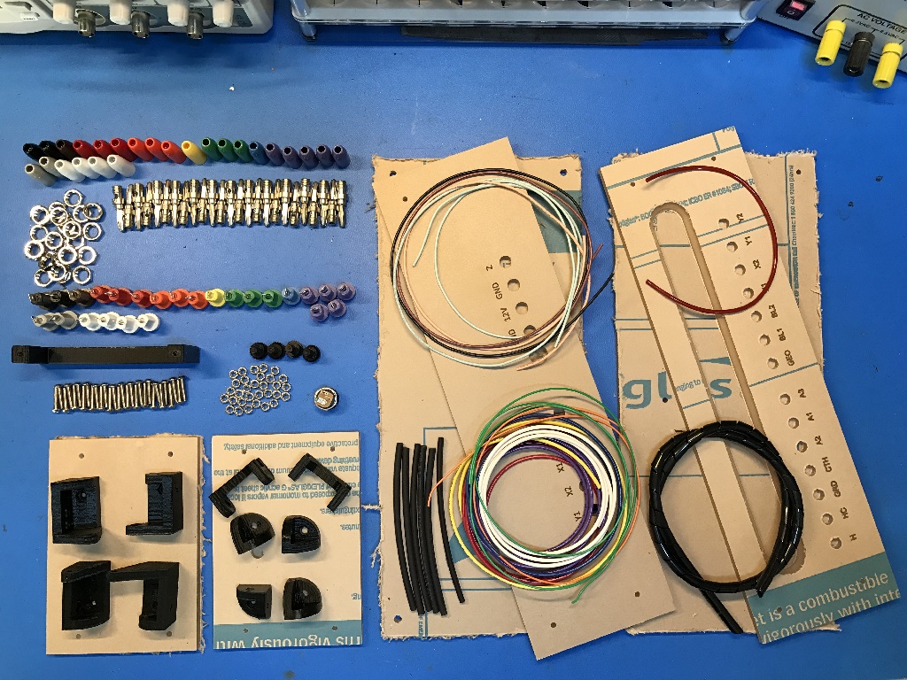
Remember!
The shop costs do not include any import or other taxes for where you live. These are yours to pay.
Built and Tested
I am also willing to completely build and test the board - with or without the case - please contact me for a cost.
Quick LinksContact
Please contact me with any questions or enquires about ordering or postage.
Quick Links