
British Octal Dekatron Rejuvenator
Introduction
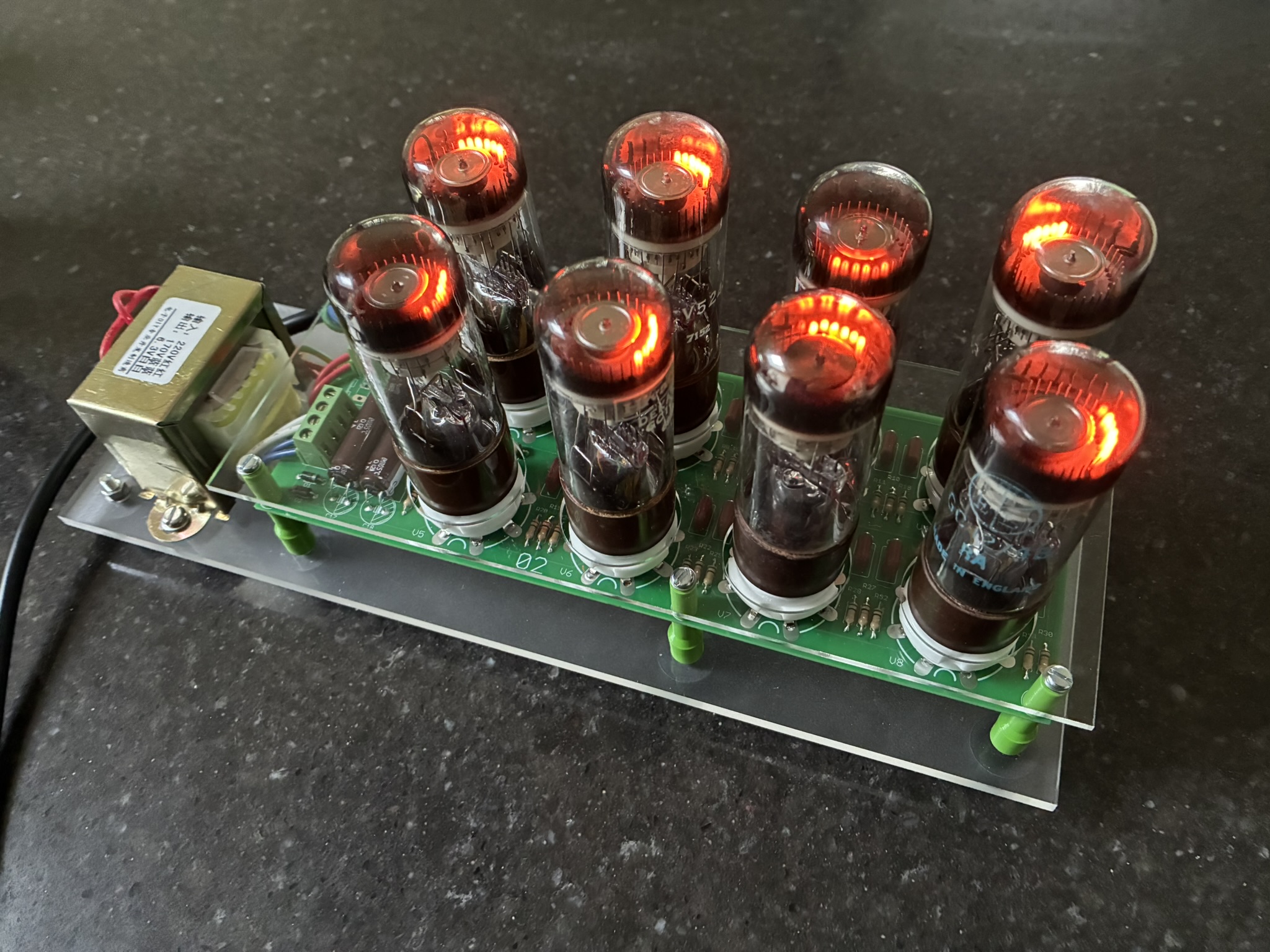
Between Sgitheach and Stock's Clocks we have anumber of projects that use British, Octal Based Dekatrons. The dekatrons are typically 50+ years old and sometimes don't want to count consistently. Some just stick and won't move. Oddly perhaps it is the NIB/NOS ones that can be the worse culprits. I suppose the time spent in storage has allowed some chemistry to occur to the surface of the cathodes and guides. Othe neon filled devices, such as nixies can also exihibit this behavour with dark or dull patches on their cathodes.
This Dekatron Rejuvenator will spin a dot round on a dekatron and, generally, I find after a few days of "exercise" the counting becomes perfect.
It is designed to work with British, octal based, neon filled, counter or computing dekatrons. So types such as GC10B, GC10/4B, GC12/4B and their variants can be rejuvenated. It will also work with the American 6802 dekatron. Selector and register dekatrons are not octal based so don't fit. Soviet dekatrons are not pin compatible.
A bare PCB is available.
Important! This project does NOT contain any AI features whatsoever. No AI help has been used in designing the electronics, designing the PCB or when writing this web page. Handcrafted!
Quick Links
Assembly
Schematic
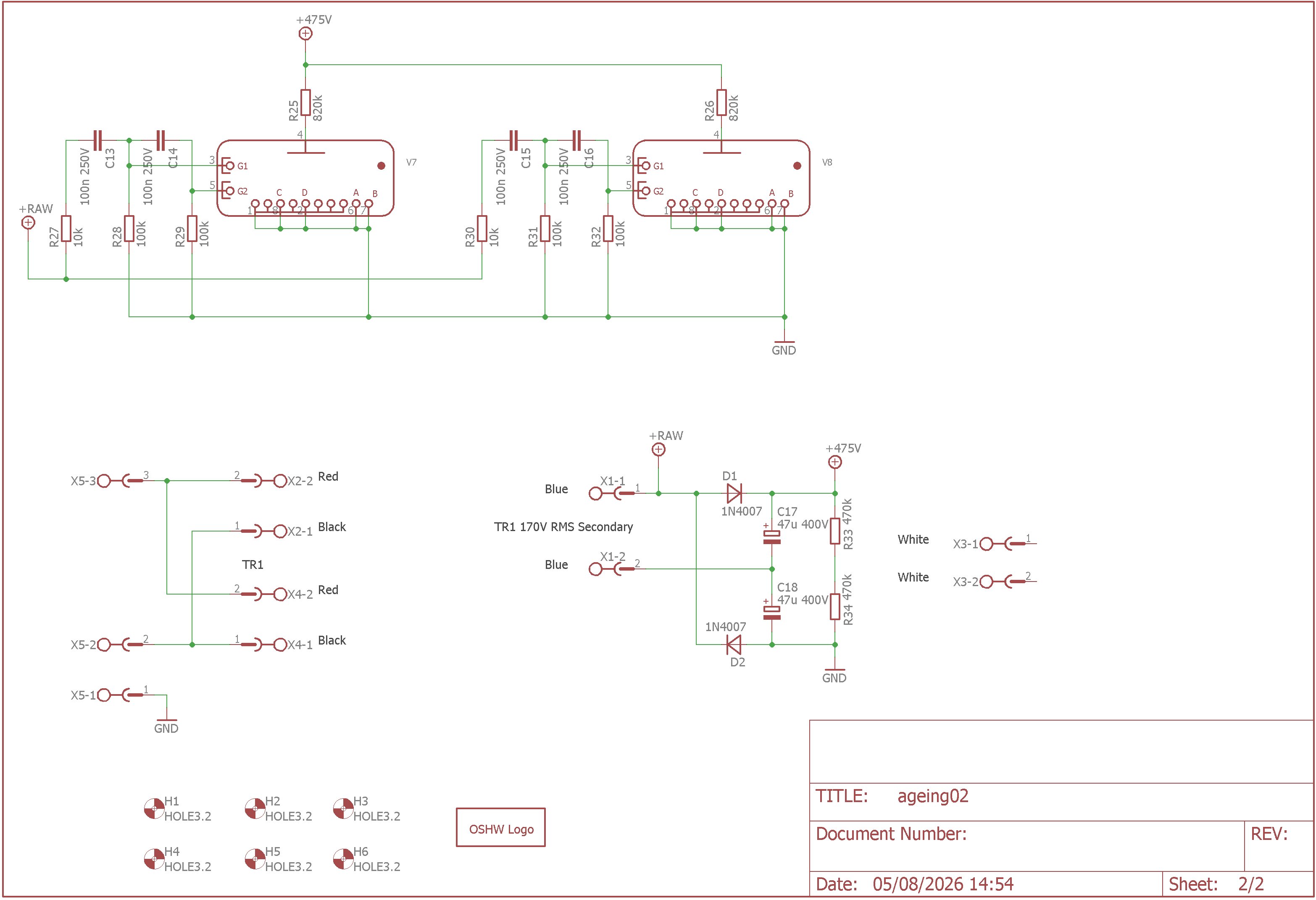
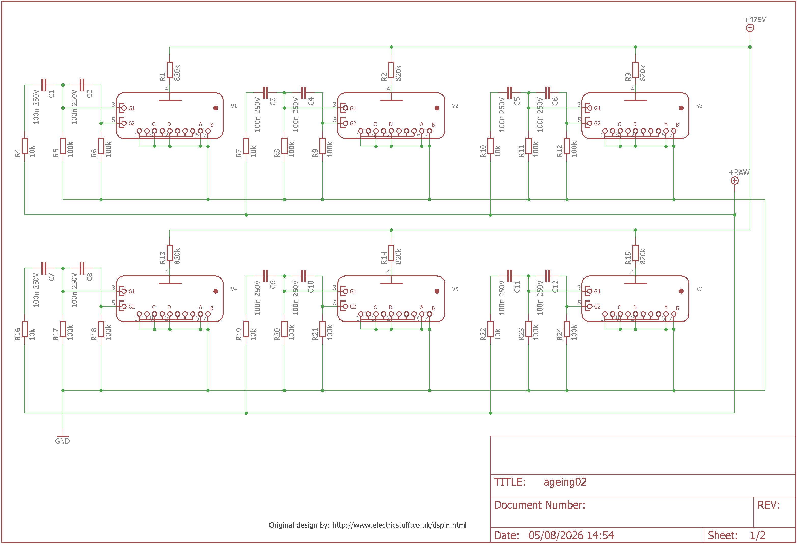
The schematic is below on two pages. The schematic image, Eagle files and Gerbers are available on the project Dropbox accessed through the Sgitheach website.
There is not much to say about the schematic and parts. It is a simple transformer based power supply to generate about 475V DC for the dekatron anodes. It uses AC from the transformer secondary to drive the dekatron guide electrodes. The rejuvenator will spin 8 dekatrons simultaneously, simply to speed up the process of rejuvenating a group of dekatrons for a project.
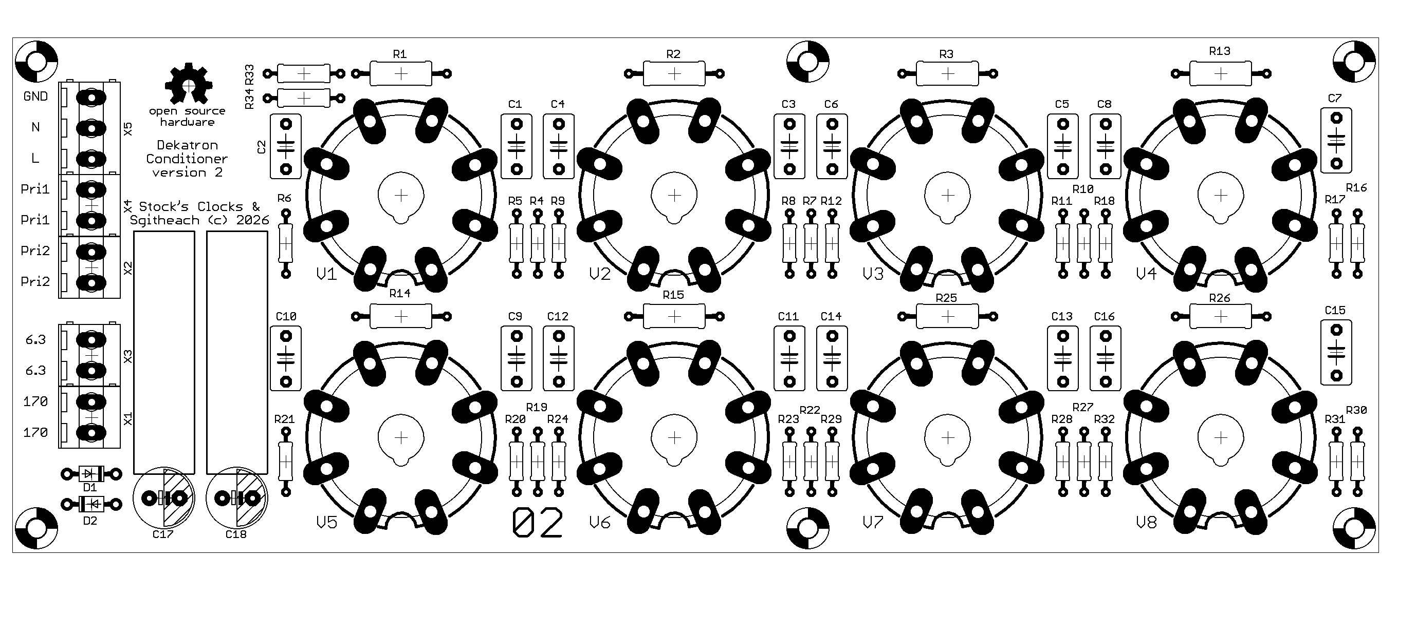
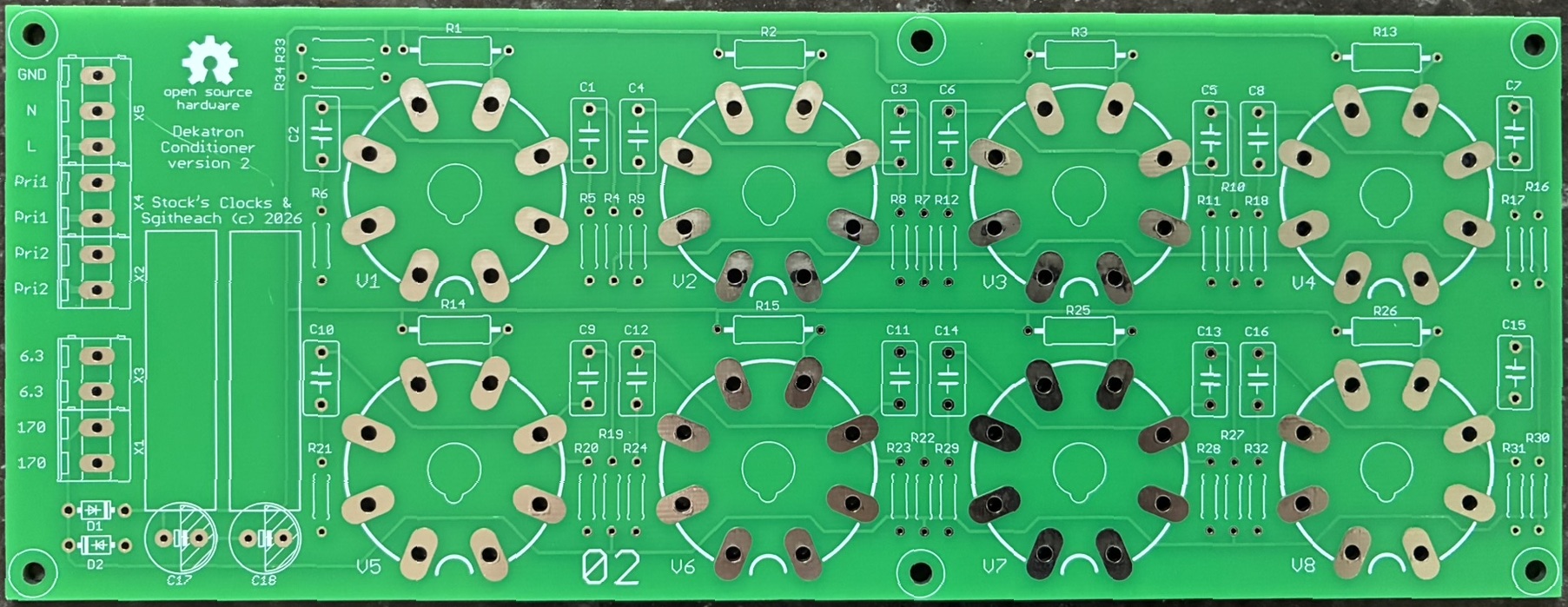
Bare board
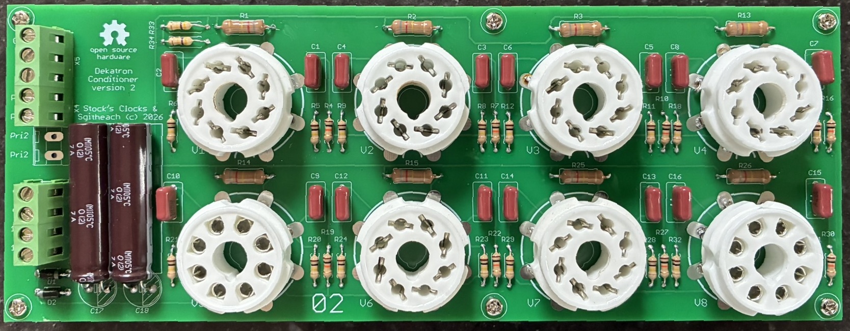
With all the parts fitted
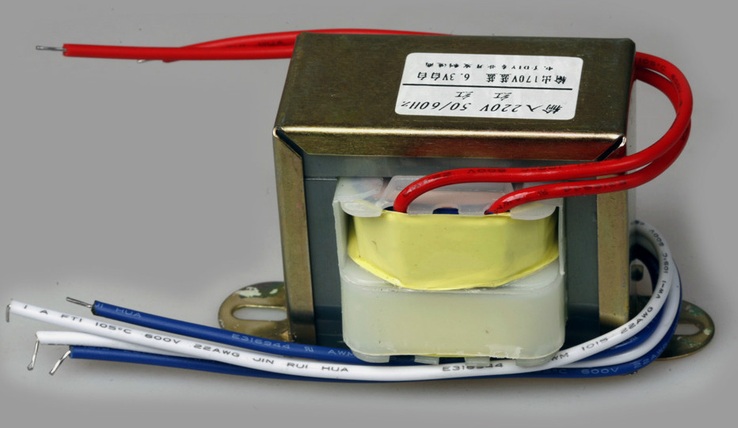
Dekatron spinners are often directly mains fed and therefore pose some hazard. In building this rejuvenator for the workshop I wanted an extra level of safety and so I used a transformer and the grounded the 0V rail on the PCB. This is not to say it is completely safe as there is still 475V DC available on the PCB. The transformer I bought from China on Ebay. It was listed as a 220V 30W Transformer 170V 6.3V for 6N3 PRE AMPLIFIER. I'm not using the 6.3V AC secondary just the 170V AC secondary. This is rectified in a fullwave doubler to give 170 x 1.414 x 2 volts. At the time of writing this webpage the same transformer is still available. It is also available with a 110V primary.
 Quick Links
Documentation
With safety in mind a very simple case was made to cover the rejuvenator PCB. The "case" only has a bottom and top but does prevent touching the PCB and offer some protection if anything is accidentally dropped on the board. It just consists of a 6.3mm laser cut acrylic base panel and a 3.2mm PCB cover. The base panel stands on some rubber feet and also carries the transformer. The PCB and to acrylic are mounted on 3D printed spacers. Considering this is just a tool for the workshop I am pleased with the construction.
The acrylic DXF cutting files and the spacer STL files are available on the project dropbox - see the next section.
Quick LinksDocumentation
You should look in the dropbox "/ Dekatron Projects / Dekatron Rejuvenator" folder.
Quick LinksFor Sale
The price of the PCBs are here.
Quick LinksContact
Please contact me with any questions or enquires about ordering or postage.