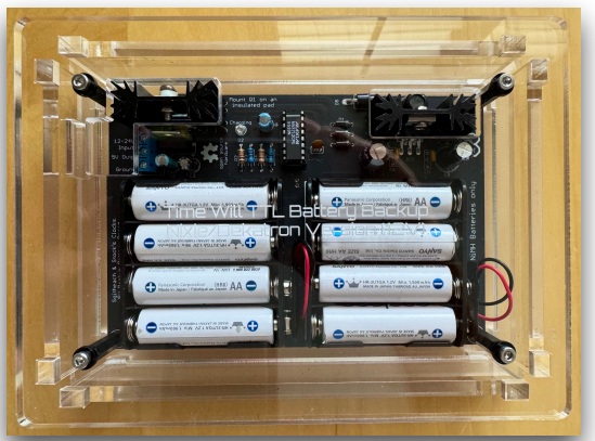
12V supply version
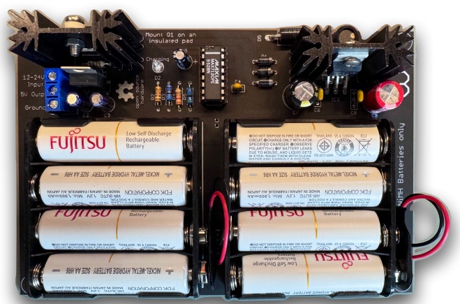
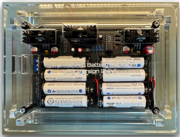
24V supply version
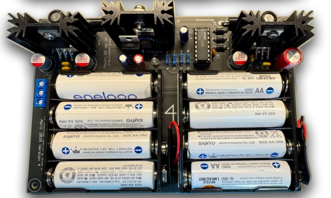
Stocks's Clocks in conjunction with Sgitheach have developed a range of clocks that do not use a microcontroller but rely instead on a swath of old style TTL chips to operate the clock. If power is removed from an operating clock the set time will be lost unless a battery is provided to power the real time clock (RTC) functioning. Modern clocks only need a small lithium cell or supercapacitor as the RTC current demand has been optimised to save power. A clock based on old style TTL has a much higher power demand and is beyond what a small battery or a supercapacitor could be expected to supply. So as an option to these TTL based clocks an optional battery backup board is available.
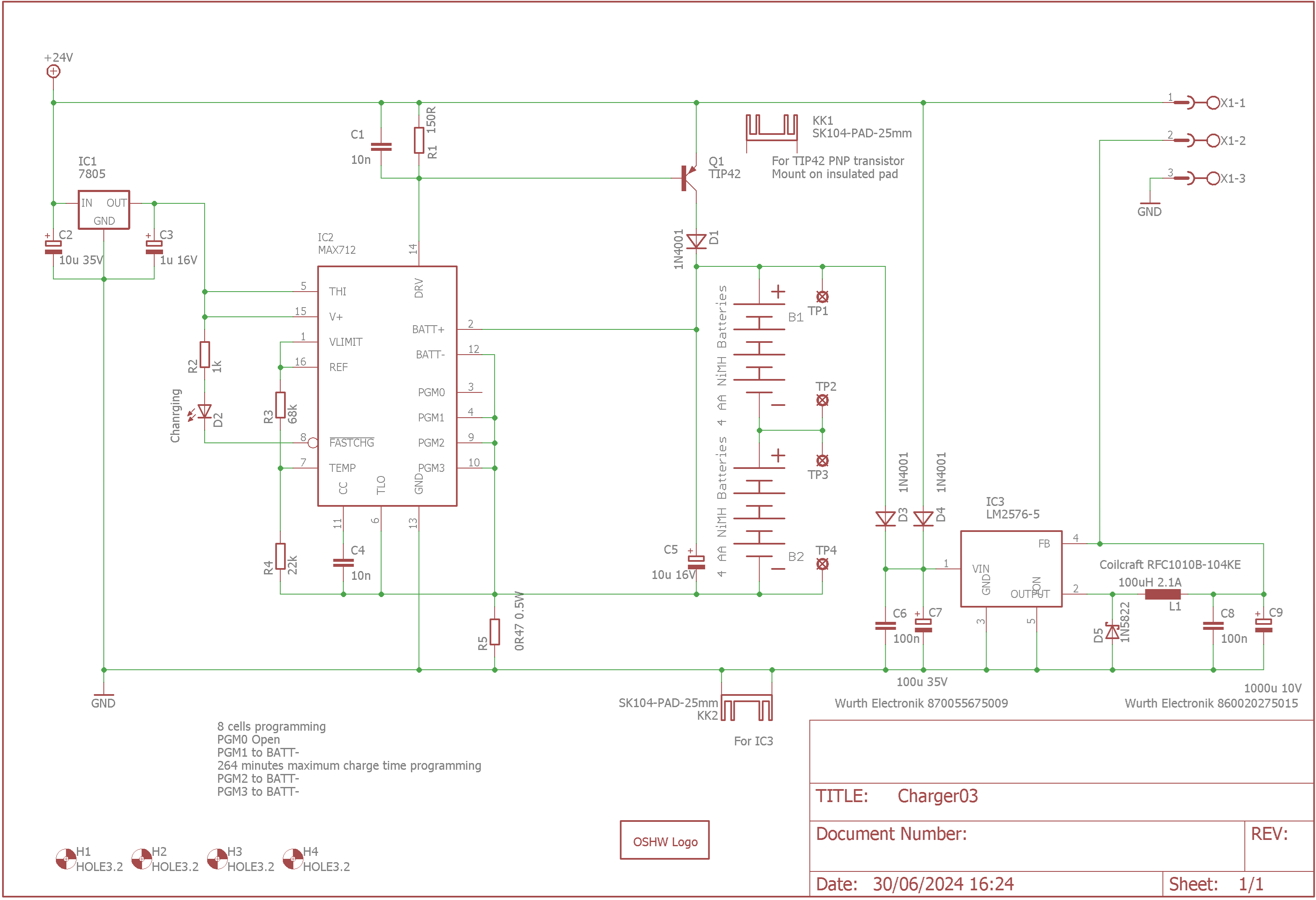
The charger section is based on the MAX712 Fast Charge Controller.
The MAX712 fast-charge Nickel Metal Hydride (NiMH) batteries from a DC source at least 1.5V higher than the maximum battery voltage. The design is fixed using 8 series cells although the MAX712 can charge between 1 and 16 cells. Cells are charged at a the lowest rate that the MAX 712 although it can charge at rates up to 4C (where C is the current equivalent to the capacity of the battery divided by one hour). A voltage-slope (ΔV/Δt) detecting analogue-to-digital converter, timer, and temperature window comparator can be used to determine charge completion. In this design the temperature is not used.
The MAX712 is powered by the DC source via an internal +5V shunt regulator. It draws a maximum of 5μA from the battery when not charging. A low-side current-sense resistor allows the battery charge current to be regulated while still supplying power to the battery's load. The MAX712 terminates fast charge by detecting zero voltage slope.
It comes come in 16-pin DIP and SO packages, the through hole part is used here. An external power PNP transistor, blocking diode, three resistors, and three capacitors are the only required external components for a minimal charger.
The MAX712 has a number of pins that are used to "programme" the behaviour of the charger. These are set as follows:
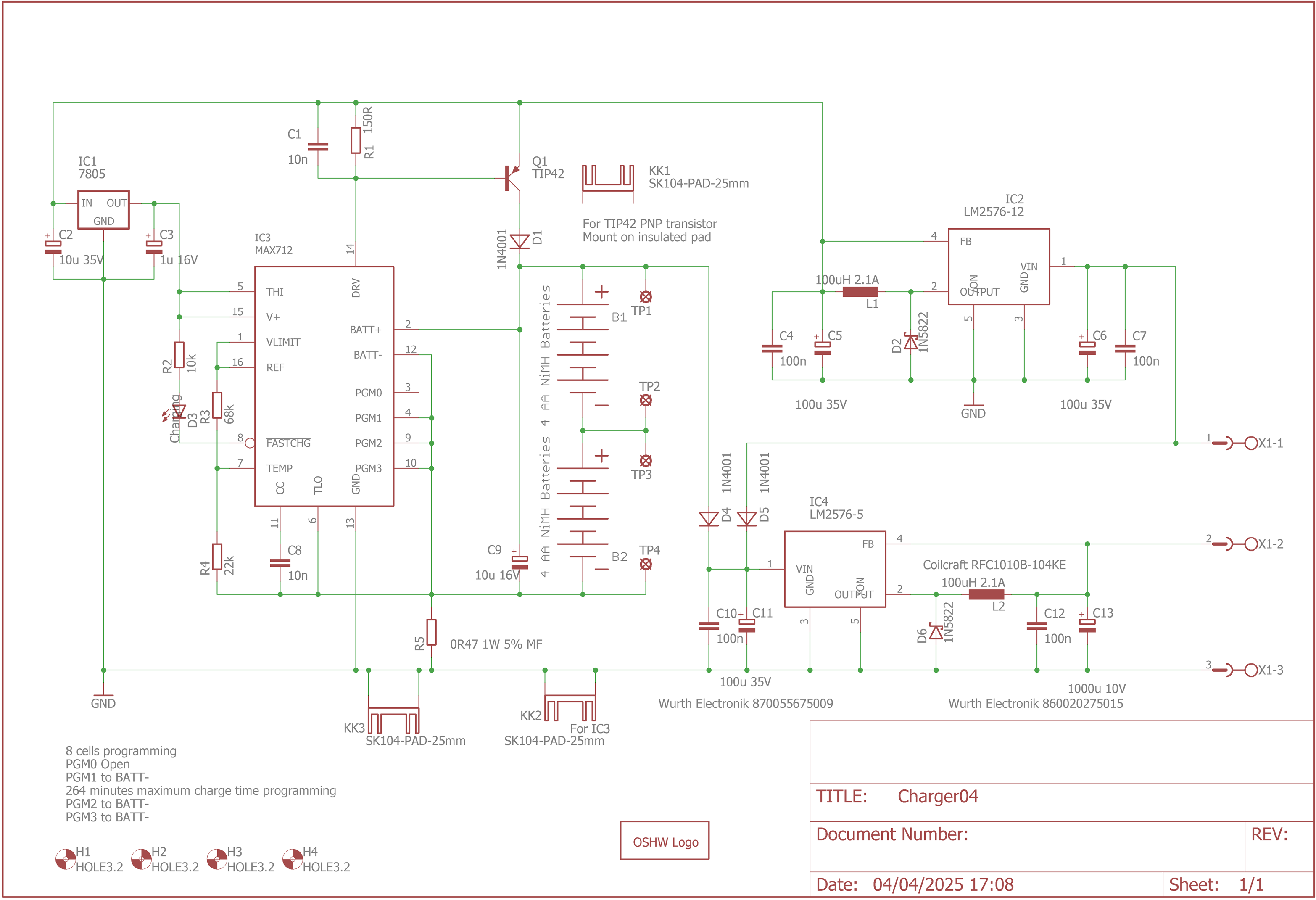
- Number of cells = 8 (PGM0 = open, PGM1 = battery negative)
- Voltage slope termination = Enabled, and
- Charging timeout = 264 minutes (PGM2 and PGM3 = battery negative)
The MAX712 operates in two modes, "fast charge" and "trickle charge". When in the fast charge mode LED D2 (see schemtic below) will be lit and it will be extinguished when in trickle charge mode.
The overall design is based on this typical operating circuit from the data sheet:

The obsolete 2N6109 is replaced by a widely available TIP42. The 5V external supply to the V+ pin, R1 here, is replaced with a 7805 regulator to give more flexibility in the input voltage range.
Rsense is set to give a maximum charge rate of about 0.5A for 2000mAHr batteries.
Other than these changes the design is the same as the data sheet design.
The 5V output supply regulator is based on a LM2576-5 switching regulator. Diodes D3 and D4 block the batteries from discharging into the DC supply or discharging when the supply is connected respectively.
The DC source can be between 12V and 24V but for optimal operation there are two versions - one aimed at a 12V supply and one at 24V. Operation outside this range is not recommended. From fully charged state, the back up power supply can provide about 100mA at 5V for 24 hours.
12V supply version
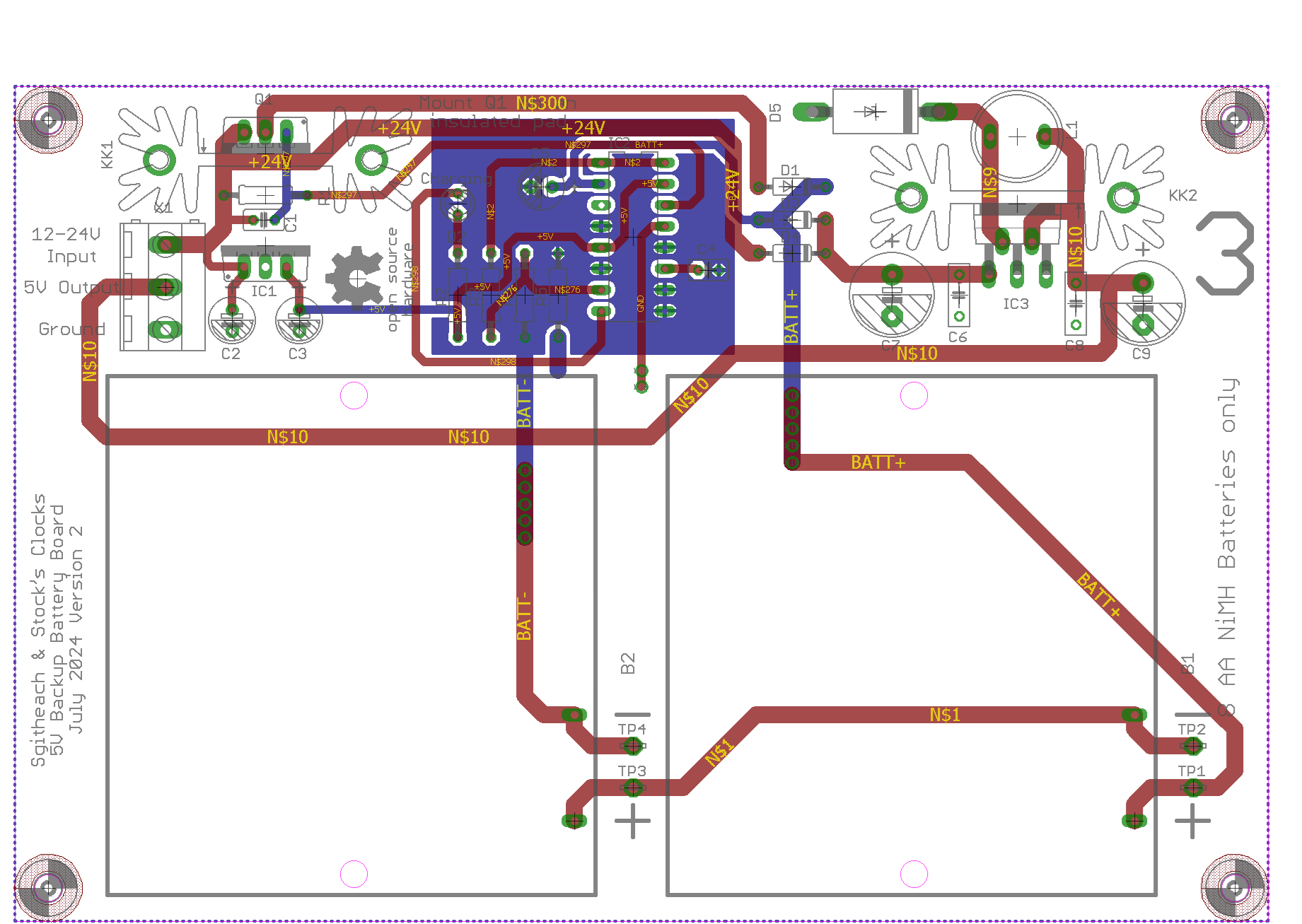
24V supply version
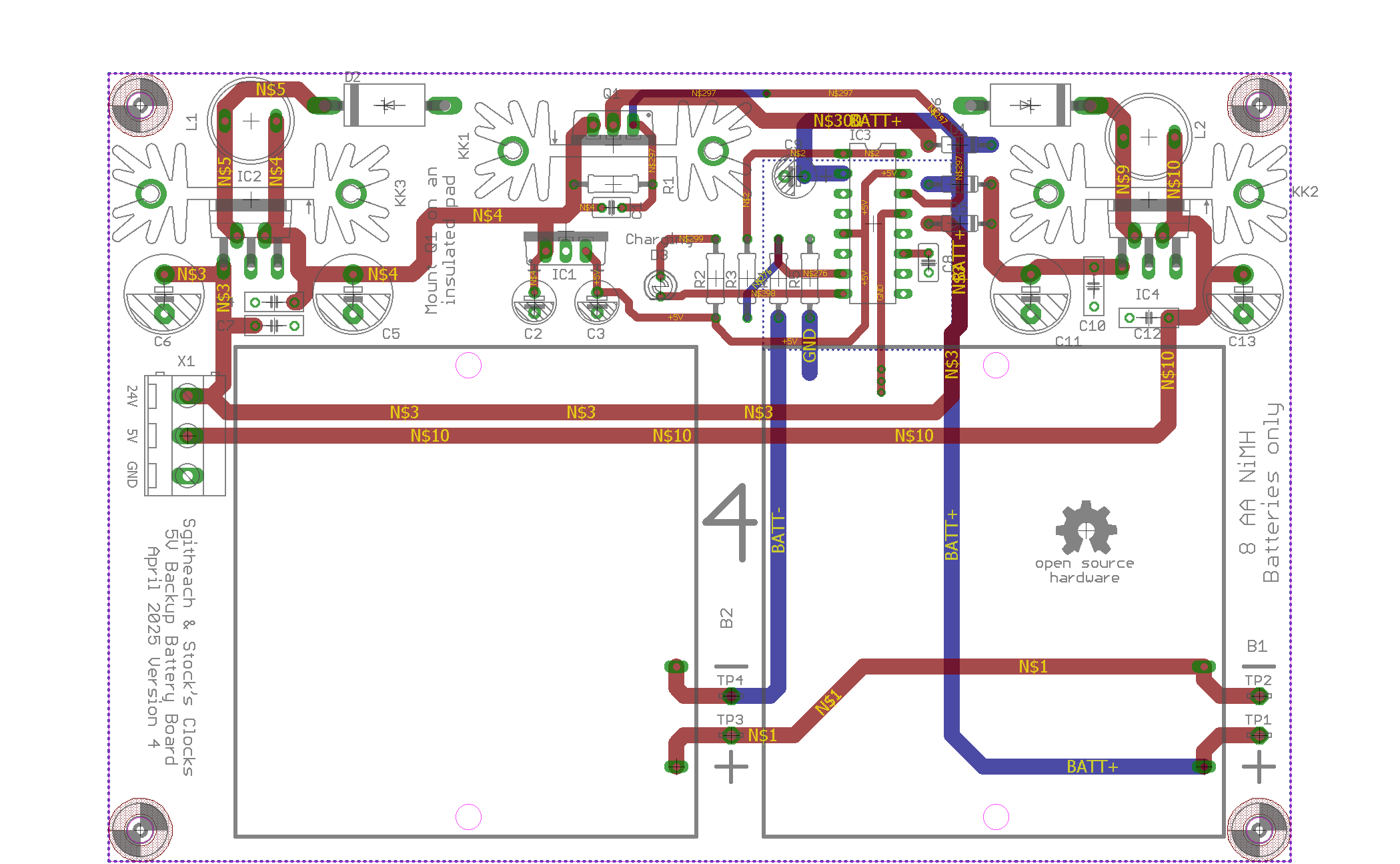
Documentation
You should look in the "/ Common Stuff / Battery Back Up and Charger" folder.
For Sale
The price of the kits and PCB are here.
Contact
Please contact me with any questions or enquires about ordering or postage.
