
A prototype VFD Approximate Clock
Introduction
Having built a number of clocks using nixies, LCDs, GLCDs and one using a VFD, I wanted to build a clock that used words to write out the time in the way you would say it: "ABOUT 7 O'CLOCK", "QUARTER PAST EIGHT" and so on. I was not the first to tread this road as I soon found out. You'll find the original approximate clock here: original approx clock!
A number of people have asked me to build them an unusual clock and this clock type looked like a good candidate. Being relatively new to using VFDs I decided to build a prototype to try out some of the components I was not familiar with but wanted to use.

So my objectives were to use:
- 16 character starburst VFDs (bought on Ebay from Obtainium! (a quick check shows they have none left)
- an atmega168 and cram as many features in as I can so see how much functionality is possible
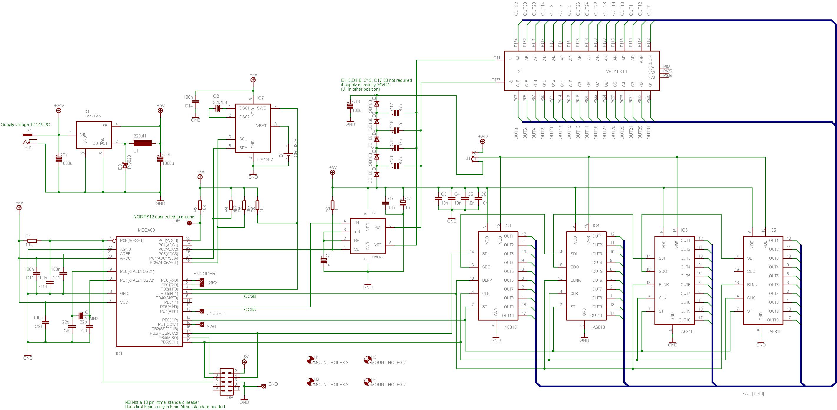
- A6810 VFD drivers using the SPI port on the mega168
- a DS1307 RTC on the TWI port - should be straight forward I've just never used this particular device
- a LM9022 driver to generate the 24VDC required by the VFD and the 4.5VAC filament drive
- wire components and not SMDs and use nothing exotic - all parts should be readily available from UK suppliers (except the VFD of course) and in the end I used one SMD - the LM9022
- PWM to dim the display and to investigate the refresh rates for the display multiplex to see if I had any problems with ghosting, strobe effects, flickering or any other unwanted effects
- multi-language support (not necessarily simultaneously).
These note are intended to outline the project (although there should be sufficient detail to build the clock if you want to). So I have not set about detailing the design to any extent. My next step will be to have a PCB manufactured and that I will detail thoroughly and I intend to make the board available on a not for profit basis (but I am now getting ahead of myself).
Schematic and PCB
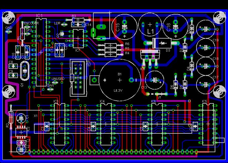
You should look in the "/VFD Projects/Approx Clock 1" folder.
The boards is double sided but for home manufacture so the through board wiring is all done using vias or leaded components where both sides are accessible. No plated through holes!
There are two components connected by wires and so not shown on the schematic a NORPS12 LDR to sense light level for setting the display brightness and a rotary encoder with a built in push button (I used an Alps encoder).
Final assembled board

Software
You should look in the "/VFD Projects/Approx Clock 1" folder.
The software was written entirely using C and compiled using the CodeVisionAVR compiler. The complete source code is downloaded. Beware - C purists beware that my C is perhaps a bit idiosyncratic but I like it. However, I hope you will find the code well commented. I have included the required libraries and you may have to play with the various paths to suit your individual set up. With help for René Eickhoff I have a German language version available and adding more langauges is fairly straight forward. Gaelic, French and Spanish are looking possible.
The complied code is available for download compiled in English or in German versions from the dropbox.
The clock software has three main modes:
- A scrolling text message displaying the time on as a 12 hour clock, pressing the push button displays a scrolling text message giving the date.
- A static "conventional" digit clock using numbers, pressing the button displays the date using numbers.
- A settings mode where the clock display parameters can be selected:
- Set Date and Time:
- Set DST - can be off, on (+1hr), automatic to EU rules, automatic to US Federal rules.
- Set year (2000-2099), month, day, hour, minute, second.
- Set Scrolling parameters:
- The Scroll lead-in and lead-out character (including none) as "*" is used in * * * FIVE MINUTES TO EIGHT * * *
- The number of lead in/out character (3 in this example)
- The scroll delay between character shifts in 10mS counts - basically "scroll speed"
- Time Formating:
- HH-MM-SS or HH-MM display
- Select the separator character to use, "-" in this example
- Whether the separator is flashed on and off each second (looks good in HH-MM format)
- Whether spaces are added to use more of the display width: 18 - 16 - 23
- Display the number digital clock in 12 or 24 hour mode: 01:30 or 13:30
- Supress the leading 0 on the hours digits: 09:47 or 9:47
- The "approximate" clock granularity 5, 10 or 15 minutes - the time steps taken between changes
- Date formatting:
- DMY, MDY, YMD formats
- Show the day of week as well on the text display: * * * TUESDAY, JUNE 10, 2008 * * *
- The separator character, spaces selection and leading 0 supression as for the time display above
- PWM dimming controls:
- Automatic or manually set.
- Two parameters for the LDR sensitivity and two more for the VFD PWM limits for fine adjustments.
- Set Date and Time:
All of these parameters are stored on the NVRAM space on the clock chip and are saved and loaded as required.
Results
I am more than content with the results…


…these are:
- Very clean display with no ghosting, strobe, flicker or other unwanted images or effects.
- The display refresh frequency is about 53Hz - increasing the speed gave no noticable improvement to the display.
- PWM dimming can be from fully bright to completely dark. The lowest practical limit is where all he VFD anodes are still lit is still a very dim display but readable in a dark room with ease.
- The LM9022 does the job it should do according to the datasheet and provides the AC filament drive and the DC for the grids and anodes and runs entirely cool.
- The SPI port talks to the VFD drivers at 10 MHz without any problem.
- A good intuitive feel to the rotary encoder and single switch to scroll through the adjustment menus.
- I have stuffed code into the mega168 and used about 80% of the flash memory without seeking to use assembler or any particlularly space efficient code so there is still room to add additional display features.
- English and German language versions available now.
The prototype has proven the basic ideas so now to move on. Bells and whistles can be added later.