
OscilloScope Clock II - Now you're serious…
Introduction
Notes, hints and suggestions on building a setting up a Scope Clock II.
Quick Links
- Main Scope Clock II description
- General Notes
- Transformer power supply
- Switching power supply
- Digital board
- Analogue board
- Programming the AVRs
General Notes
Here I'm assuming that you have received the PCBs from me. If you've made them yourself, using some form of prototype board or had them
professionally made, then the potential faults will be different.
Remember that my boards are home brewed boards and there are likely to be faults that you wouldn't see on professional boards (sorry). The main faults to look out for are hairline scratches through the tracks (where whether I or the LJ printer has scratched the image), tracks with bridges between them (dirt on the image), copper swarf from drilling still attached and possibly causing a bridge (mostly a problem on the DS boards on the side I drill through to) and undrilled holes (where I failed to spot a drill point). I have looked for all these faults and rectified any I have spotted but it doesn't hurt to keep a look out. In particular look for faults on the DS top when fitting components that then obscure the board, especially IC sockets, which will be a devil to fault find and correct later. You will also find my pads are a bit small and the ring is sometimes partly drilled away; you have to run a fillet of solder around to ensure you connect the lead to the track (again sorry).
In general I have drilled a hole for a component or just a pilot hole if it is a mounting point or for a large component so you can drill the hole out to the diameter you want. So initially as you tackle each board you need to check than any component with a fat lead (electrolytics, battery holder, some of the diodes, fuse holder) to see if its hole needs increasing in diameter. The biggest holes I've drilled are typically 1.2mm and the smallest 0.6mm (for components I know have a small lead). You'll need some larger holes and nuts and bolts to mount the two trannies on the PSU tidy board, and whatever spacers you are going to use.
Throughout these notes "50/60Hz" means either 50Hz or 60Hz depending on your mains frequency.
Building & Testing the Mains Transformer PSU
SAFETY FIRST
Because this is a PSU operating at 50 or 60Hz there are some pretty big smoothing capacitors that are charged between +320V and -800V. If you touch them it will hurt! There is mains present on the board (115V or 230V AC). So the board has potentials and stored energy that could be FATAL. I'm assuming that you are comfortable with this and have sufficient experience to work safely.
There are bleed resistors across all the smoothing caps but they are not low value and it takes several minutes to bleed the charge away. So it make good sense to check with a multimeter that the capacitors have discharged before diving in. Switch off - go make a cup of coffee. Please don't crowbar discharge the capacitors they are quite large and the resultant shock to the system can fry some of the chips - the HV PSU is connected to the deflection amps, the deflection amps are connected to the DACs, the DACS are connected to the digital stuff (you know the tune).
Also the cans of the capacitors are exposed at the end where the can is designed to fail if it is overloaded. The can is normally connected to the -ve lead, so the +ve HT supply smoothing capacitor is not a problem but the cans of the capacitors in the -ve HT supply will be at voltages upto about -800V. A common technique is to put small discs of PVC electrical tape (in a tasteful colour) across the exposed metal to reduce the risk.
One last safety comment, perhaps the most important, the scope clock must be correctly earthed. It must be wired using a three core mains lead and plug.
To continue…
My suggestion is you build and test the PSU first. Obvious perhaps. I don't think I have any particular hints for building the PSU as it is the simplest and most straight forward. There are a number of wire links to put in and a row of wire links between the two boards. The second PSU tidy board has 5 wire links that selects 115V (3 links) or 230V (2 links) operation. Details on the schematic and PCB image. When you have built the PCB you can apply power and check the voltages are about right. The voltages may be a bit high as it is off-load. None of the voltages are that critical anyway ±10 or 20% is not a problem. Much greater deviation suggests a fault and should be investigated.
When you are satisfied that the voltages are ok and nothing is getting too hot then you can connect up a CRT to check it is working and the spot brightness is controlled and the tube will focus. Connect the heater (if you are using a CRT that has one side of the heater internally connected to the cathode then you need to put this common lead to the side that requires the cathode connection and the heater to the "live" 6.3V side). Connect the control grid, cathode and the focus anode. Connect the final anode and the four deflection plates together and connect to the +320V test point. Apply power and you should find that you cannot get a spot what ever position you put the brightness pot in! Now apply 5V to the blanking input (the optoisolator is turned on to unblank the tube) (I used a 6V lantern battery) (you can use a higher voltage battery or PSU but you will need an extra resistor). You should now be able to control the brightness and with a normal brightness spot, focus it to a dot. Turning the supply to the blanking input on and off should blink the spot.
An interesting exercise is to move the CRT near to the transformers (within a few inches) you may see the dot extend out to a small line (may be 3 or 4 dot widths in length). This will give you a first indication or how close you can get the tube to the transformers when you come to case the clock.
Quick LinksBuilding & Testing the SMPS
Blah blah
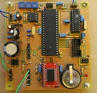
Quick LinksBuilding & Testing the Digital Board
I suggest the next card to build and test is the digital card as, if you have an oscilloscope, you can check that the thing is running and the output signals are all there as it only requires power to operate. The ribbon cable to the analogue card only carries digital power and outputs.
The only holes to enlarge will be the four corner mounting holes and possibily the battery holder. Because my home brew boards are not PTH you have to put links in as vias between the two sides. In many places (I count 19 on the digital card but I may have missed some) there are two vias very close together. This is to put a wire link as through. I bend a U out of a resistor lead offcut and insert through the top and bend the leads over underneath then solder. It gives a neat finish. These link the top ground plane to underneath ground sections which are often isolated islands so the link provides the connection to the components using that island. This is how they appear - just NE of R5
There are a lot of vias (three in this image) where you need to insert wire and solder both sides. There are vias underneath IC2, IC3 and IC5 so these must go in before the IC sockets are fitted. Normally I do a quick continuity check with the multimeter for such vias that will be hard to repair later on. A number of vias use component wire leads and so these must be soldered both sides. And sometimes a component is only connected to a top track. I normally find and fit all of these components that need to be soldered both sides or soldered top side only before moving on to the other components. The centre pin (ground) of IC4 is an example of a component lead that is soldered both sides but it will become difficult to get to once a lot of the surrounding components have been put in.
Then fit the rest. For IC2 I used a 0.6" wide 28 pin IC socket and cut it down to 20 ways. I used the 0.1" header pins and a SOIC carrier to hold the IC (I hate SMDs).
I would normally apply power (two AC leads, any way round, and one ground lead back to the PSU) before plugging is any IC into its socket and check that the 5V rail is there and the 5V appears on each socket as required.
Set the three pots to mid-position.
You can now plug in the rest of the ICs and burn the HEX files and set the fuses in the two AVRs (see later). If you are going to use an oscilloscope to tune the circle generator bandpass filter then you just burn the clock HEX file; if you don't have a'scope and are going to use the software mmethod described later, then you burn the set up HEX file.
When you have programmed the AVRs I think a few checks are worth while to demonstrate that all of the signals that should be present are there. If you have programmed the main clock HEX file and have a speaker hooked up then you should get a triple chime when the card is powered up.
Don't spin the rotary encoder as you might just select the blank screen and many of the signals listed here will disappear.
If the clock software has been burnt into the mega, and not the set up software then I would check the following (check 1. can be done with a multimeter or an oscilloscope but checks 2. to 7. require a 'scope):
- The 1Hz TP next to IC2 should have a 5V p-p 1Hz signal on it (suprise). This will show that the mega and the RTC are basically working together.
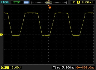
- The 50Hz TP next to R12 and C11 should have a trapizoidal square wave on it of 50/60Hz about -0.5 - +5.5V peak to peak.
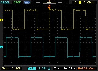
- Look at pins 2 & 3 on the tiny26 - you should find 31.25kHz 50:50 square wave on each. If you use a dual beam 'scope you should see that they are 90° phase shifted. These are the sine and cosine signals to the circle generator bandpass filters.
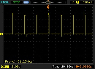
- On pin 4 you should find a 31.25kHz pulse at 12.5% on period. This is the circle start sync signal back to the mega.
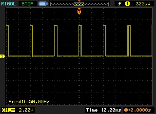
- On pin 9 you should find a simple burst (the simplicity or complexity depends on the screen being displayed with a repetition of 50/60Hz. This is the beam blanking signal from the mega.
- On the blanking output you should find a more complex burst at 50/60Hz repetition. This is the beam blanking with the octant selection added.
- On SV2:
- pins 1 & 2 bursts at 50/60Hz - shape selection bits
- pins 3 & 7 signals as of 3 above
- pins 4, 5, 6 & 8 bursts at 50/60Hz - signals to the DACs
- pin 9 ground, pin 10 +5V.
I suggest these tests are worth doing as they will eliminate later fault finding with the more complex analogue card.
Quick LinksBuilding & Testing the Analogue Board
Having built the digital card then the analogue card is just a repeat and I have nothing to add.
I trust you have seen that NP0 capacitors are required for the four capacitors in the circle generator filters - if you use capacitors with a significant thermal coefficient then the display will drift apart as the room temperature varies. Even with them you will find there is a "warm" up period as the image aligns itself.
I'm going to give two tuning procedure for the circle generator: one using a dual beam 'scope (the easy method) and one if you don't have a 'scope. The purpose of the adjustments is to tune the two bandpass filters in the circle generator to exactly the circle frequency (31.25kHz) so that they are in the correct phase with the circle start sync pulse and 90° phase from each other.
Tuning the circle generator - 'scope method
There is no reason why your should not try out the mega software method as well of course.
Step 1 - Tuning the sine generator
Power the clock up and let things warm up for 10 minutes or so.
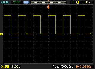
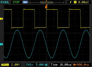
Put the dual beam scope channels on TP4 (output of IC10) and the incoming square wave on pin 3 of SV1. There is a track on the top of the board to C31.
You will see a square wave and a sine wave in rough antiphase. Adjust R49 to bring the two signals into exact antiphase. As you do this the amplitude of the sine wave will increase and should be about 20V p-p ie -10V to +10V swing. Be as accurate as you can, I find it helpful to increase the scope Y gain for the sine wave and get the sine wave crossing points symetrical on the square wave. It'll look like this:
You'll find the adjustment quiet fine, hence the 20 turn pot.
It is possible that the adjustment of R49 takes you up one end of the travel. If so check that the square wave is 31.25kHz. You may need to change the value of R53. I don't expect this to be necessary I only mention this in case component tolerances require it. I've not enough experience with these circuits to know as yet.
Step 2 - Tuning the cosine generator
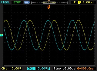
Repeat for the cosine filter using TP2, the top track between pin 7 of SV1 and C9 and adjusting R39.
If you put the dual beam scope onto TP2 and TP4 it'll look like this:
Step 3 - setting the output levels roughly
Set R44, R54 and R55 to give about 5V p-p i.e -2.5V to +2.5V on TP3, TP6 and TP5 respectively. The pots should be about mid-travel and final adjustment of these pots is made using a test screen on the CRT.
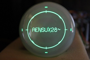
This completes the circle generator tuning using a 'scope. The set up continues below after I have described the tuning without a 'scope. But it is necessary to find the test screen. Hopefully, the image on the CRT will be recognisable as the Sgitheach title page; adjust the deflection amplifier position and size pots to get the image roughly filling the CRT; adjust the brightness and focus for a good image. On the Sgitheach title page click the rotary encoder. This will take you to the first system menu screen. You will see a flashing underline, rotate the encoder until the line is flashing under "test screens". I'm hoping you will find things readable enough to see the text. A test screen will appear … the story continues below.
Tuning the circle generator without a dual beam 'scope
To tune the circle generator the mega needs to be programmed with the tune.hex file found in the code.zip file. The test.hex software contains four test screens to help the adjustment of the sine bandpass filter (R49) and cosine filter (R39).
Coarse Tuning
The circle generator output amplitude pots should be set to mid position (R44, R54 and R55).
Power the clock up and let things warm up for 10 minutes or so.
Adjust the x and y position and size pots on the deflection amplifiers to get the + shape centred on the CRT. Adjust the brightness and focus for a good image. Something like this:
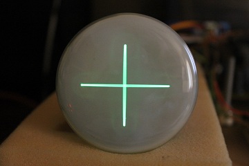
Adjust the sine bandpass filter tuning pot for the maximum length of the horizontal bar. It may be necessary to adjust the x deflection amplifier gain as the maximum point is found.
Adjust the cosine bandpass filter tuning pot for the maximum length of the vertical bar. It may be necessary to adjust the y deflection amplifier gain as the maximum point is found.
Fine Tuning - Sine
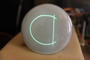
Move the rotary encoder so that a C shape and a vertical line appears:
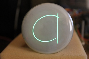
Note that the ends of the C shape are not verticallty aligned (they may both be one side or the other side of the vertical line or either side as in this photograph). The vertical line is there to give a reference. Carefully adjust the sine tuning pot so that the ends of the C are aligned vertically:
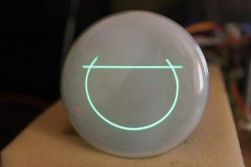
Fine Tuning - Cosine
Move the rotary encoder so that the C shape is moved through 90° and the line becomes horizontal. Carefully adjust the cosine tuning pot so that the ends of the C are aligned horizontally:
Move the rotary encoder so that the final test screen is displayed (the test screen is also available within the main clock software so adjustments can be repeated).
Final Adjustments
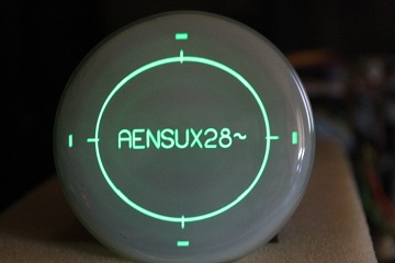
Rotate the encoder until this screen appears:
The four lines at 12, 3, 6 and 9 o'clock represent the rough edges of the drawn area. If they are off the screen and the centre circle is too big then reduce the X or Y gain to bring them in.
There are four other short lines at 1:30, 4:30, 7:30 and 10:30. when the adjustments are complete they will lie under the circle.
Adjustment is now about playing with the three amplitude controls on the circle generator (don't touch the two bandpass filter tuning pots!!!) and the x and y deflection amplifier size pots. My suggestion is you first adjust each amplitude pot by rocking it side to side and you will see some aspect of the display change.
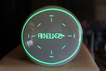
In my case here, your's may be different, the circle is too large - it should be inside the four outer markers and should lie roughly on the sloping lines. So I first adjust the sine amplitude pot (R55) and the cosine amplitude pot (R44) to bring the circle in:
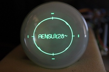
The image is now a bit too small. So I adjust the deflection amplifier x and y size pots and the position pots to centre the image:
The four outer markers are just on the start of the curvature of the CRT. Eventually you will need to experiment to see how large you can make the image on your particular CRT without starting to get distortion or out of focus near the very edge.
The inverted sine amplitude (R54) only changes the Y amplitude of lines with a negative slope so as you rock it the angle of the N and X \ lines appears to change. So you use this pot to make the N join up and the X look symetrical.

The sine amplitude pot (R55) effects lines with a positive slope (including vertical and horizontal) so you adjust this so lines meet up as required. The E is a good letter to look at.
The cosine amplitude pot (R44) effects circles and arcs height. So look at the S, 2 and the 8 and get the centre parts of the arcs to line up.
While you are doing this you may find that the screen grows in one dimension, for example increasing the Y amplitude of circular components might elongate them into ovals, so reduce the overall Y gain using R22.
There is some iteration between the three amplitude controls and the two gain controls but there is little interaction as such. When you have done this you may need to make further small adjustments to bring the 2:30 etc lines underneath the circle but hopefully you will have seen how the controls work now.
Pretty close now! Some final tweaking can take place when the main clock screens or other test screens are displayed.
Don't touch the bandpass filter tuning pots!!!
Chime adjustment
Before I continue I should make a general comments about the menus - there are a lot of them. You should be in the system menu at the moment, most clock faces have menus which you get to by clicking when it is displayed. A menu that has nothing to save will have a "Return" item, a menu that is going to save something to eeprom or the RTC will have an "Accept" and a "Cancel" item. There are radio button type menu items where you select on from a short list by clicking on it, there are checkboxes that you turn off and on by clicking on it and numerical values. You click on the line and the number will start to blink, the encoder will wind it up and down between preset limits (an hour can only be 0 to 23 for example). When you have set the value you click again.
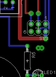
Back to chime adjustment, on the system menu rotate the encoder and click when Chimes is underlined.
On the chimes menu rotate the encoder past a very long list (I think this is the longest menu) and you will come to five items, single chime, double chime, triple chime, chime six and calibrate. Click on single chime and you should get a … single chime. You can adjust the loudness pot R11 on the digital card. You cannot turn the volume to zero (but there is a menu item to turn all chimes off and you can turn chimes off between two given hours). If you don't like the range and want it quieter or louder then you may need to change R8. Adjusting the oscillator frequency using R10 affects both the pitch and the duration of the chime. Again if you want a different range than I have set then you may need to change R7 or C8. The range available goes from long, deep and slow to very quick and chirpy. Obviously you play to to see what you like hitting the single, double and triple chimes menu items.
To explain what "calibrate" is about: one of the limitations of this chip in this application is that you cannot retrigger it until the current play is entirely finished. The time period you have to wait is the length of the triple chime even if you triggered a single chime. So I have connected the output of the chime generator into the analogue compare pins of the mega and you can adjust the comparison voltage using R6. When you press calibrate the triple chime will sound and the analogue compare will locate the end of the chime. I add a bit extra and this is then the calibrate value that you'll find near the top of the menu (you can change this value but it shouldn't be necessary, and if you do, the value will be overwritten when you next calibrate). You can then press "chime six" and the clock will attempt to play six single chimes, which you count. Between each single count is a short pause and you can make an adjustment to R6, press calibrate, press "chime six" and see if the delay between each single chime is too long or too short for your taste. But the effect is subtle; I have considered replacing R6 with a fixed resistor and doing away with the adjustment; you may find that the pot in centre position works just fine. The important fact is that you count six chimes. If you get five or less then the delay has been made too short. It is essential to press calibrate each time the frequency or compare reference voltage is changed so the new timing can be established.
Overall I like this chip, it gives a triple chord with a decaying amplitude and is worth the hastle to use it for such a cheap and simple solution. The timbre and quality of the sound is very dependant on the quality of the speaker.
Lastly, a word more about the encoder, you may find that a rotate or click operation is missed. The interrupts for the encoder inputs have just about the lowest priority and mega has a lot going on keeping the screen refreshed at 50/60Hz. I judged that an odd missed click from the encoder was worth it for an entirely flicker free screen. A future scope clock should have a work around but that is not for now!
Other setting up
RTC adjustment
Time, Date - you need to enter these as UTC (or GMT if you like) or the astronomical functions won't work. You can set time to local standard time and time zone to zero and ignore the astronmical errors.
DST - you can select EU rules, USA (Federal) rules or force the clock to standard or daylight saving manually.
Latitude and longitude
These are only used by the astronmical functions so leave the default values (my house) if you wish.
Other menus - playtime
The other menu items should be straightforward if you play with them. You cannot damage the clock with any menu item and you cannot shut the clock down to a point where you can't recover the position. But there is a load default menu option which will put you back to "factory settings" (also you will loose all of your settings if you reburn the mega without setting the "preserve eeprom" on).
Quick LinksBurning the AVRs
The fuse setting given below are calculated using this excellent tool.
I use the AVRDUDE software with (typically) an Atmel MkII programmer. Because of the wide range of programmers and software I cannot give much advice on setting the fuses and programming the hex files. The code.zip file contains two batch files that use AVRDUDE to program the AVRs.
Tiny26 Fuses
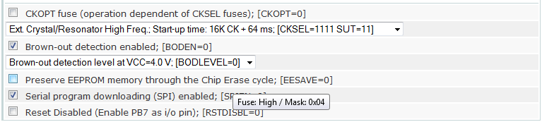
The AVRDUDE arguments are: -U lfuse:w:0xff:m -U hfuse:w:0xf4:m
Mega1284p Fuses
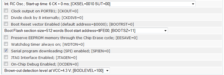
The AVRDUDE arguments are: -U lfuse:w:0xc2:m -U hfuse:w:0xdf:m -U efuse:w:0xfc:m
Quick Links