
OscilloScope Clock II - Yet More
Introduction
This pages continues the story of the development of Scope Clock II. In particular, a low cost PSU and experiments with trace rotation for a rectangular CRT.
Quick Links
- Main Scope Clock II description
- Introduction
- Demonstration low cost PSU
- Scope Clock II low cost PSU
- Trace Rotation
- PSU Calculations
- Demonstration PSU Parts List
- Scope Clock II PSU Parts List
A Demonstration Low Cost PSU
Acknowledgements
To Mike Moorrees for his many designs using the MC34063 switcher chip and, in particular, his CRT tester which showed that it is possible to power a CRT using it, inspirational stuff.
To Martin Forsberg for a great deal of help trying to understand the MC34063 switcher design, factors that lead to instability and overcoming such instability. Martin also corrected some schoolboy errors in my design calculations (he says, red-faced).
Demonstration Build
My requirements for the first build were to provide power for an unpublished Scope Clock (unpublished so far). The power requirements are not dissimilar to the Scope Clock II requirements (these voltages are relative to analogue and digital ground unless stated):
- +275V at 25mA for the deflection amplifiers and final anode
- -660V at 20mA for the cathode supply
- 6.3V at 0.6A for the heater supply with one side of the supply at cathode potential
- at least -75V relative to the cathode for the blanking supply to the control grid
- +5V relative to the cathode for the blanking amplifier operating supply
Given that my main goal of the design was "low cost", it implies that no custom wound transformer can be used and so I must use a standard transformer. (I have ruled out the direct-mains option on safety grounds.) Many standard transformers come with two independant secondaries so could one be used for the cathode grid and heater supplies and the other used for deflection amplifier and other low voltage requirements for the remaining digital and analogue cicuits? Here's how …
The Eagle files can be downloaded here.


Assembled demonstration PSU board:

Running a scope clock (6Л01И CRT):

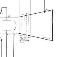
But the image is not square with the sides of the CRT - time for some Trace Rotation!
 Quick Links
Scope Clock II Low Cost PSU
Ok, the PSU works well with a simple scope clock, now to trial it with Scope Clock II. The main difference between the demonstration PSU above is that the blanking amplifier is moved onto the power supply card.
The Eagle files can be downloaded here.


This PSU is basically suitable for any CRT that will operate with < 1kV final anode voltage; a 6.3V or 4V heater and no PDA. Adjustment to component values are essential to set correct anode voltage, heater voltage and maximum current, grid voltage and focus voltage. The complete parts list is given in an Annex below together with the modified values for a few other CRTs.
Assembled Scope Clock II PSU board, the demonstration board with the blanking amplifier added:

Changes to Scope Clock II
- Digital Card - None
-
Analogue Card - Omit R36, R37, R38 & R40 (100k resistors in the HV+ PSU section) and replace one with a wire link;
omit D17 and D19 (120V zener diodes in the HV+ PSU Section). And fit either:
- the 1M astigmatism potentiometer and connect the point where C18 and C28 are joined to the wiper of the potentiometer; or
- two (new and un-numbered) 470k resistors in place of D17 and D19.
- Mains Power Supply - Omit entirely ☺
Trace Rotation Experiments
Blah Blah Blah
Quick LinksAnnex 1
Annex 1 - Demonstration PSU Calculations for 6Л01И CRT
This Annex presents the required conditions, calculations and determined component values for the three switchers to generate the heater supply, the positive supply for the deflection & final anode supply and the negative voltages for the cathode/grid supplies.
In each case I use an input voltage of 15V ±5% assuming the supply is from a 12Vrms transformer secondary, rectified using a bridge rectifier (12 × 1.414 − 2 × 0.7 = 15.4) and smoothed.
Most of the calculations presented below use this calculator. Other calculators (untried by me) are here and here.
I do use the "official" OnSemi calculator for the heater convertors as well. The OnSemi calculator doesn't allow boost convertors with outputs higher than 40V so is not usable (or is that abusable?) for the HT supplies.
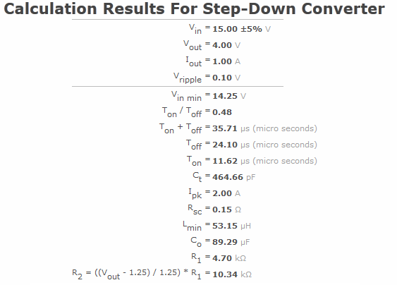
6.3V 0.6A Heater Supply
Conditions I used are 15V ±5% supply voltage, required output 6.3V at 0.6A with <0.1V ripple. The operating frequency was adjusted to use a 470pF timing capacitor and a reasonable inductor.
Calculation results are:
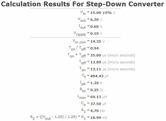
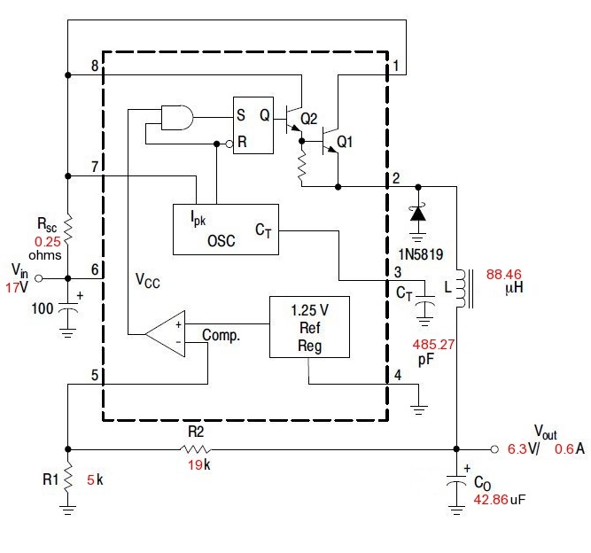
So I have used four 1R resistors in parallel for the sense resistor, a 100μH 1.2A inductor, 47μF output capacitor and a 1k and a 18k resistor in series for the voltage feedback.
The OnSemi calculator gives more or less the same result and predicts an efficiency of 80%.
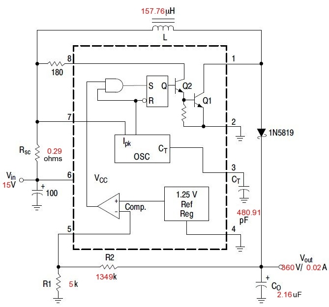
275V Deflection Amplifier & Final Anode Supply
Conditions are 15V ±5% supply voltage, required output 275V at 25mA with <1V ripple. The operating frequency was adjusted to use a 470pF timing capacitor and a reasonable inductor.
Calculation results are:
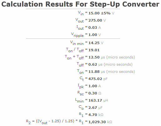
So I have used three 1R resistors in parallel for the sense resistor, a 220μH 1.2A inductor, 4.7μF output capacitor and a 470k and a 560k resistor in series for the voltage feedback.
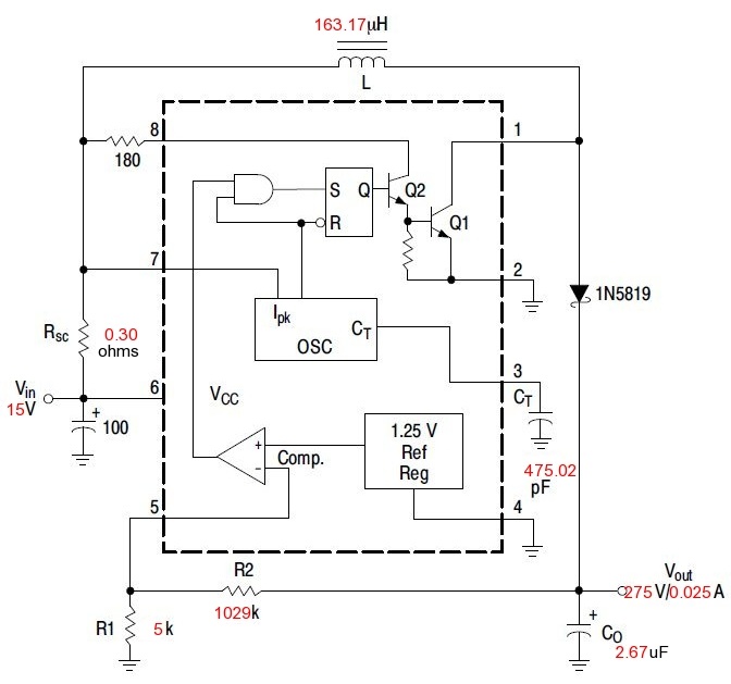
360V Supply to the Cathode and Grid Voltage Doublers
Conditions I used are 15V ±5% supply voltage, required output 360V at 20mA with <1V ripple. The operating frequency was adjusted to use a 470pF timing capacitor and a reasonable inductor.
Calculation results are:
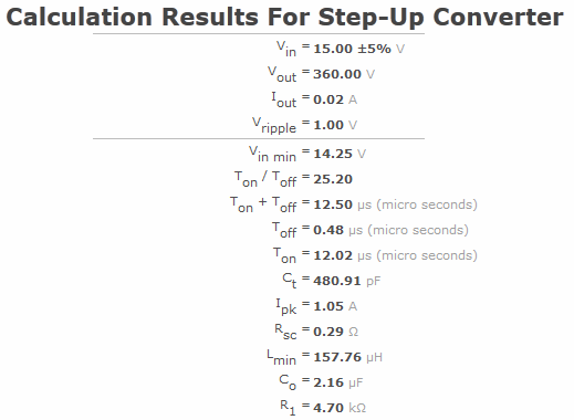
So I have used three 1R resistors in parallel for the sense resistor, a 220μH 1.2A inductor, 4.7μF output capacitor and two 680k resistors in series for the voltage feedback.
Afterword - 4V 1.2A Heater Supply - Untested
Conditions I used are 15V ±5% supply voltage, required output 4V at 1.2A with <0.1V ripple. The operating frequency was adjusted to use a 470pF timing capacitor and a reasonable inductor.
Calculation results are:
Ipk exceeds 1.5A so the design as it stands is not suitable. An additional pass transistor capable of handling the higher current is often used. However, the OnSemi calculator allow the maximum average output current to be raised by increasing the inductor size (the normal calculation is to minimise the inductor size) so as to reduce the ripple current. The calculation results are that a 480μH 1.3A inductor is required, the sense resistor should be five 1R resistors in parallel. This is all untested so far and I need to do further work to optimise (additional transistor vs larger inductor) and prove the 4V heater supply option.
Quick LinksAnnex 2 - Demonstration Power Supply Board Parts List
Values to suit 6Л01И CRT or similar. All resistors are 0.25W 5% carbon
| Part | Description | Farnell Code | Rapid Code | Dimensions |
| C1, C10 | 220u 25V | 1219468 | low ESR type Panasonic EEUFM1E221 8mm dia |
|
| C2, C11, C18, C19 | 100n | 9750983 | ||
| C3, C9, C13, C14 | 4u7 400V | 1907180 | Panasonic ECA2GM4R7 8mm dia |
|
| C4, C15 | 2200u 25V | 9692215 | 13mm dia | |
| C5, C16 | 10n | 9411852 | ||
| C6, C17, C22 | 470p | 9411771 | ||
| C7, C20 | 47n 450V | 1890497 | I bought mine on ebay | |
| C8, C12 | 0.22u 400V | 9751246 | 17 x 7 mm case | |
| C21 | 47u 10V | 9452427 | 6mm dia | |
| R1, R12 | 180R | 62-0355 | ||
| R2-R5, R13-R16, R24-R27 |
1R | 62-0312 | omit as instructed | |
| R6, R17 | AOT | fit link to start | ||
| R7, R20, R28 | 4k7 | 62-0389 | ||
| R8, R21, R30 | 1k | 62-0373 | ||
| R9, R19 | 470k | 62-0437 | ||
| R10 | 560k | 62-0439 | ||
| R11, R18 | 1M | 62-0443 | ||
| R29 | 18k | 62-0403 | ||
| ferrite beads | see R6, R17 | initially omit | ||
| L1, L2 | 220u 1.2A | 1749114 | Panasonic ELC11D221F 10mm dia |
|
| L3 | 100u 1.2A | 1749108 | Panasonic ELC11D101F this part is 1.8A 10mm dia |
|
| B1, B2 | 50V 2A | 9380957 | Multicomp 2KBP02M + ~ ~ - pins |
|
| D1, D3-D6, D8 | UF4007 | 4085310 | 47-1008 | |
| D2, D7 | 1N4148 | 9565124 | 47-5608 | |
| D9 | 1N5819 | 7429304 | 47-2566 | |
| IC1, IC2, IC4 | MC34063 | 1077180 | 82-1088 | OnSemi or TI preferred |
| IC3 | 78L05 | 1467367 | 47-3612 | TO220 cased 7805 will fit |
| Q1, Q3 | IRF740 | 1653662 | 47-5616 | |
| Q2, Q4 | 2N3906 | 1574372 | 81-0281 | small pnp cbe |
| X1 | 7 way pin header | to Scope Clock card see note 1 |
||
| X2 | 5 way pin header | from transformer and supply earth see note 1 |
||
| X3 | 2 way pin header | to CRT heater see note 1 |
||
| TR1 | 2 x 12Vrms 15VA toroidal |
9530258 | 88-3783 | I bought mine on ebay |
| 8 pin DIL IC holders for IC1, 2 & 4 | 22-0107 | |||
Notes:
- 0.1" pin header strip with everyother pin removed; wires soldered and covered with heatshrink tube
Annex 3 Scope Clock II Power Supply Board Parts List
All resistors are 0.25W 5% carbon. The values in the first table suit the 2AP1 CRT the table that follows gives alternative values for some other CRTs.
| Part | Description | Farnell Code | Rapid Code | Dimensions |
| C1, C12 | 220u 25V | 1219468 | low ESR type Panasonic EEUFM1E221 8mm dia |
|
| C2, C8, C9 & C13 | 100n | 9750983 | ||
| C3, C11, C16, C17 | 4u7 400V | 1907180 | Panasonic ECA2GM4R7 8mm dia |
|
| C4, C18 | 2200u 25V | 9692215 | 13mm dia | |
| C5, C19 | 10n | 9411852 | ||
| C6, C20 & C24 | 470p | 9411771 | ||
| C7, C21 | 10n 450V | 1890497 | ||
| C10, C14 | 0.22u 450V | 9751246 | 17 x 7 mm case | |
| C15 | 100u 100V | 9451595 | 13mm dia see note 4 |
|
| C22 | 1u 400V | 9693319 | 6mm dia | |
| C23 | 47u 10V | 9452427 | see note 4 6mm dia |
|
| R1, R2 | 10R | 62-0329 | ||
| R3, R19 | 180R | 62-0355 | ||
| R4 | 390R | 62-0363 | ||
| R5-R8, R21-R24, R35-R39 |
1R | 62-0312 | omit as instructed see note 4 |
|
| R9, R27 | AOT | fit link to start see note 5 |
||
| R10 | 1k | 9354298 | Bourns 3362P series; see note 2 |
|
| R11 | 390R | 62-0363 | ||
| R12, R30, R40 | 4k7 | 62-0389 | ||
| R13, R31 | 1k | 62-0373 | ||
| R14 | 470k | 62-0437 | see note 4 | |
| R15 | 560k | 62-0439 | see note 4 | |
| R16 | 1M | 62-0445 | see note 4 | |
| R17 | 0R | link see note 4 |
||
| R18 | 33k | 62-00409 | ||
| R20 | 27k | 62-0407 | see note 4 | |
| R25 | 270k | 62-0431 | ||
| R26 | 500k | 9354395 | Bourns 3362P series; see note 3 |
|
| R28 | omit | |||
| R29 | 470k | 62-0437 | ||
| R32 | 330k | 62-0433 | see note 4 | |
| R33, R34 | 680k | 62-0441 | ||
| R41 | 18k | 62-0403 | see note 4 | |
| R42 | 1k | 620-373 | see note 4 | |
| ferrite beads | see R9, R27 | see notes 5 & 6 | ||
| L1, L2 | 220u 1.2A | Panasonic ELC11D221F 10mm dia |
||
| L3 | 100u 1.2A | 1749108 | Panasonic ELC11D101F this part is 1.8A 10mm dia see note 4 |
|
| B1, B2 | 50V 2A | 9380957 | Multicomp 2KBP02M + ~ ~ - pins |
|
| D1, D3, D5-D8, D10 | UF4007 | 4085310 | 47-1008 | |
| D2, D4, D9 | 1N4148 | 9565124 | 47-5608 | |
| D11 | 75V 400mW zener | 1097240 | NXP BZX79-C75 see note 4 | |
| D12 | 1N5819 | 7429304 | 47-2566 | |
| IC1, IC4, IC5 | MC34063 | 1077180 | 82-1088 | OnSemi or TI preferred |
| IC2 | 78L05 | 1467367 | 47-3612 | 78L05 is Ok |
| IC3 | 6N137 | 1021197 | 58-0598 | |
| Q1, Q6 | IRF740 | 1653662 | 47-5616 | |
| Q2 | BC327 | 9558489 | 47-5456 | |
| Q3, Q7 | 2N3906 | 1574372 | 81-0281 | small pnp cbe |
| Q4, Q5 | ZTX558 | 9526676 | ||
| X1 | 4 way pin header | to analogue card see note 1 |
||
| X2 | 11 way pin header | to CRT and external controls if fitted see note 1 |
||
| X3 | 5 way pin header | from transformer and supply earth see note 1 |
||
| X4 | 2 way pin header | blanking signal from digital card see note 1 |
||
| X5 | 4 way pin header | to digital card see note 1 |
||
| TR1 | 2 x 12Vrms 25VA toroidal |
1785738 | ||
| 8 pin DIL IC holders for IC1 & 3 - 5 | 22-0107 | |||
Notes
- 0.1" pin header strip with every other pin removed; wires soldered and covered with heatshrink tube
- The brightness control (R10) can be either a 1k trimpot on the PCB or an external mounted 1k pot connected using X2(1-3)
- The focus control (R26) can be either a 500k trimpot on the PCB or an external mounted 500k (or 470k) pot connected using X2(7-9)
- Value given for 2AP1 CRT see table below for values for other CRTs
- Supression of gate ringing perhaps leading to instability
Alternative CRTs
The following table presents values for other CRTs (the 2AP1 CRT is repeated for completeness). For each CRT the key design value is given followed by the calculated component values to achieve the design condition. The process is perhaps more simple than it appears but the complexity is necessary to achieve a flexible design. The decisions are:
- Use the heater voltage and current to determine values for R35-R39, R41 & R42, L3 and C23.
- Use the anode voltage to determine the +HT voltage (must be in the range 250-275V) and the -EHT voltage (the difference). Use the +HT voltage to determine values for R14 & R15. Use half the -EHT voltage to determine values for R33 and R34.
- Use the -EHT value and the focus voltage range to determine values for R17, R20 & R32.
- Use the minimum grid voltage to determine values of D11 and C15.
The other component values given in the table above should be useable. But I cannot guarantee that other changes won't be necessary for a CRT that I've not tested.
| Value | 2AP1 | DG7/32 | DB7-5 | DH3/91 | E4103/B/4 | 6Л01И |
| Heater voltage | 6.3V | 6.3V | 6.3V | 6.3V | to do | to do |
| Heater current | 0.6A | 0.3A | 0.3A | 0.55A | blah | blah |
| C23 | 47u 10V | 22u 10V | 22u 10V | 47u 10V | ||
| R35-R39 | 3x 1R | 2x 1R | 2x 1R | 3x 1R | ||
| R41 | 18k | 18k | 18k | 18k | ||
| R42 | 1k | 1k | 1k | 1k | ||
| L3 | 100uH 1.2A | 100uH 0.9A | 100uH 0.9A | 100uH 1.2A | ||
| Anode voltage | 1000V | 700V | 900V | 500V | ||
| +HT voltage | 275V | 250V | 250V | 250V | ||
| -EHT voltage | -725V | -450V | -650V | -250V see note 1 |
||
| R14 | 470k | 470k | 470k | 470k | ||
| R15 | 560k | 470k | 470k | 470k | ||
| R21-R24 | 3x 1R | 2x 1R | 3x 1R | 2x 1R | ||
| R33 | 680k | 560k | 820k | 470k | ||
| R34 | 680k | 270k | 390k | 470k | ||
| Focus voltage | 200-300V | 0-120V | 200-300V | internal | ||
| R17 | 0R | 0R | 0R | omit | ||
| R20 | 27k | 22k | 27k | omit | ||
| R32 | 330k | link (0R) | 330k | omit | ||
| Grid voltage | -75V | -120V | -50 | -50 | ||
| C15 | 100u 100V | 100u 160V | 100u 63V | 100u 63V | ||
| D11 | 75v 400mW | 120V 400mW | 49V 400mW | 49v 400mW | ||
Notes:
- Omit the voltage doubler (C10, C11, D5, D6, R16), omit the focus pot (R26) and put a link in place of R16.