Introduction *** warning project incomplete and stalled ***
We have never quite be satisfied with alarm clock radios - the colour was not right, they didn't set the time automatically, they were slow/fast, the display at night was too bright/dim, never the right size AND most of all they lacked the beauty of glowing neon…
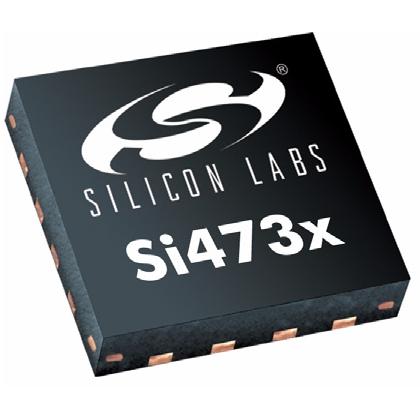
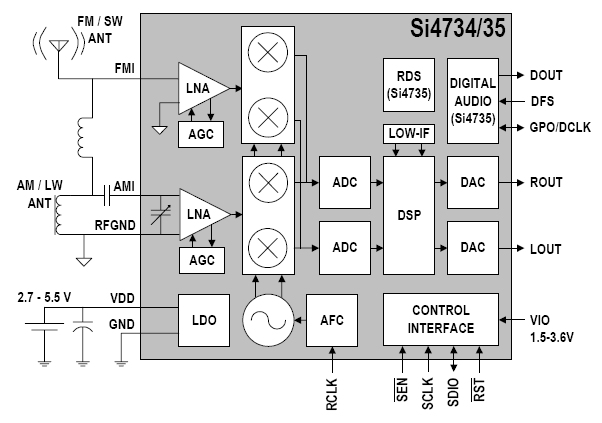
The answer was obvious - build your own nixie - alarm - clock - radio. The problem was always to find a radio to use. I also needed to automatically synchronise the time to a good time source (not difficult). I was pondering what to use when Elektor magazine published a development radio using an AVR and Silicon Labs SI4735 DSP radio chip. This chip shown in the swatch above measures 3mm x 3mm and has 18 contacts round it and the ground underneath. Ok for people with access to the sort of SMD equipment needed to solder this chip - but basically beyond my means. But Ha!!! Elektor sell this chip already mounted and tested on a DIP carrier. So now things got interesting. The chip is a LW-MW-SW-FM receiver - and for FM - offers stereo decoding and RDS information. RDS can carry a time signal so the possibilty of a RDS set clock, FM receiver (mono only) became a reality. A quick order to Elektor delivered the chip on its carrier and the project entered the experimental phase.
First Experiments
I built a simple PCB to take the receiver chip carrier, 3.3 V psu for the chip, bidirectional level convertors for the TWI (I²C) lines as the chip is not 5V tolerant and a simple audio amplifier. I hooked it to a test AVR board (I used a mega32 in the tests but in practice a smaller mega would have just been as good. The software manual for the chip took some reading, but Elektor provided some test code (in BASIC unfortunately which I immediately ditched in favour of C) and in one evening I was tuning up and down the FM band listening to the local FM stations. Another evening and I had started to get the RDS data stream out of the chip and, most importantly, the date and time data. So I moved onto the full clock design.

Specification
The clock design had become:
- hh:mm nixie display - hh:mm:ss not required
- FM only receiver - no AM bands - stereo not required
- Clock time set using RDS
- Clock time preserved using a battery backed clock chip - I will store set up details in its NVRAM
- Simple audio amplifier
- LDR to detect room brightness to auto dim the display
- A selection of buttons, switches and a rotary encoder to set the alarm, tune the radio, adjust the volume etc.
- USB port to set up all of the other clock functions that don't change often
- Nixie (Z560M) direct drive chips(HV5522)
- 3.3V, 5V and 180V DC power supplies
I choose direct drive for the nixies, rather than multiplex, as I was concerned that any generated mush might interfere with the FM radio. I did use switching convertors for both 5 VDC and 180 VDC power supplies but I was still concerned with a mush problem. But another clock with both convertors did not interfere when brought close to the FM receiver.
The rest is now straightforward as each of the projects sections I have previously built in other clocks or projects. The HV5522 chip I have used in the red box clock. The power supplies are now very repeatable designs, the clock chip I have used frequenty and lastly, the radio chip was tested.
Display card

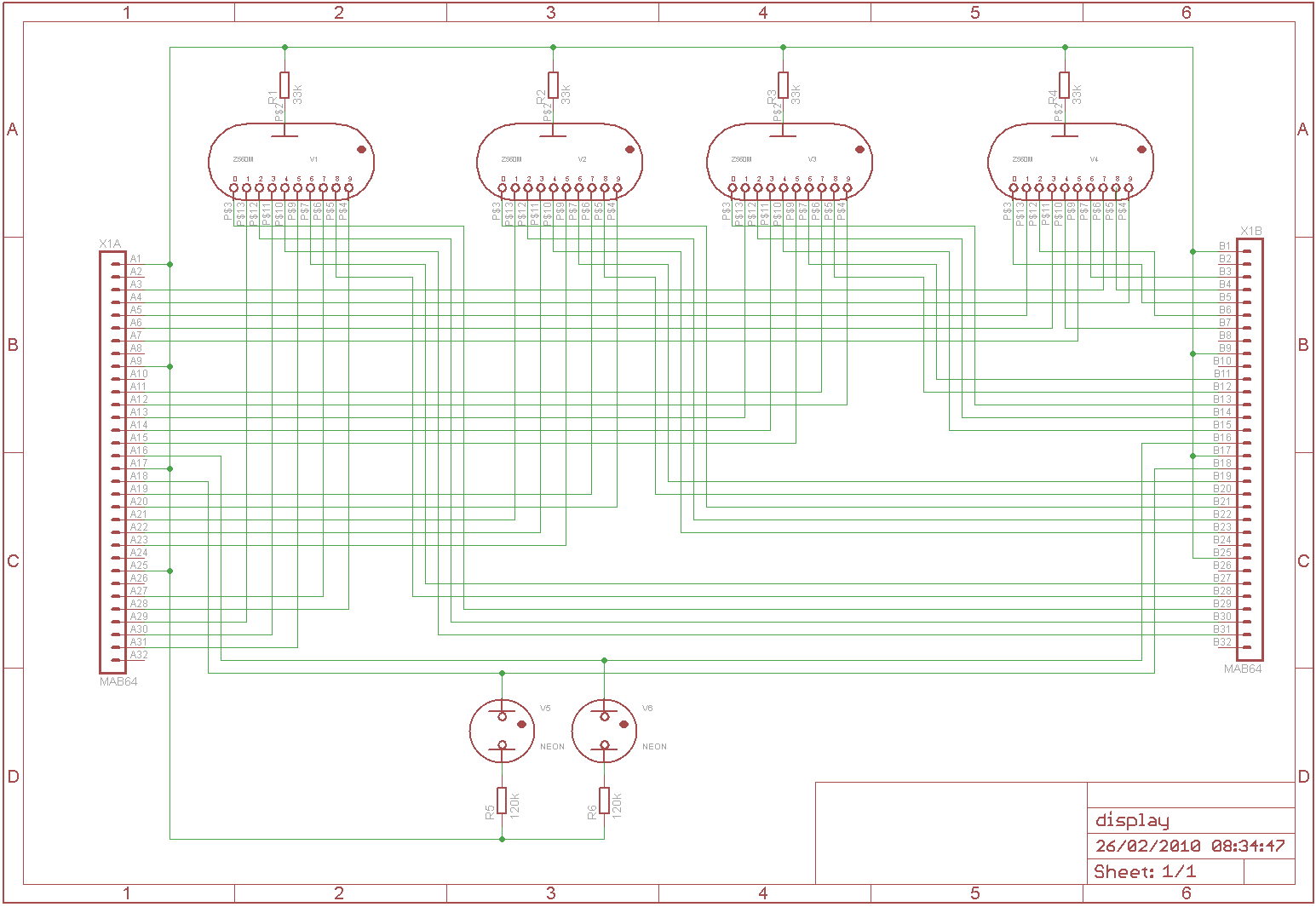
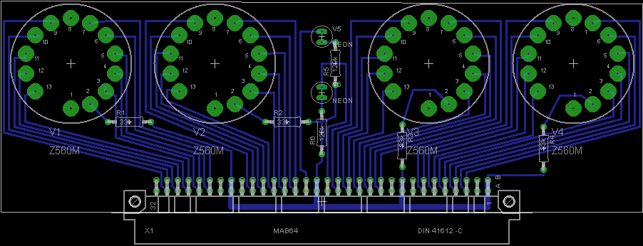
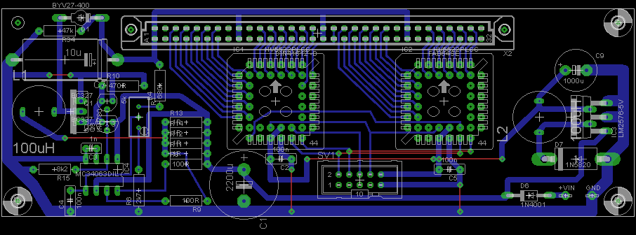
This is a very simple card as it just has to carry the 4 nixies, two colon neons and the 6 anode resistors. I used a 64 multiway right angle connector to give a good solid connection to the driver/psu board. I paid no attention to any logical arrangement of the cathode connections (here or on the driver card) as I intended to sort out those details in software. The advantage is that it led to a very simple PCB layout. For ease I interspersed the 180 VDC connections. I had ways to spare as 40 cathodes + 2 neons + 180VDC would require 43 of the 64 available connections.
Eagle schematic and layout
Right click and "view image" or "save image as" to look at this schematic in full.
Display Driver and PSUs
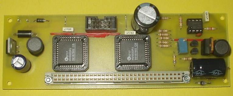
The second card carries the mate of the 64 way connector and two HV5522 high voltage driver chips. They are brilliant in nixie clock designs as they have:
- 32 open drain HV tolerant outputs
- Available in non-SMD packages
- Simple two wire serial interface (data+clock) and I intended to use the microcontroller's SPI port to drive this
- A blanking input which can be fed with a PWM signal to dim the display
- A latch pin so that the (8 bytes of) data can be fed into the two devices and then transfered to the display in one go
Eagle schematic and layout
Right click and "view image" or "save image as" to look at this schematic in full. The Eagle files are in the download section below.

Microcontroller, USB, Clock, Radio and Amplifier

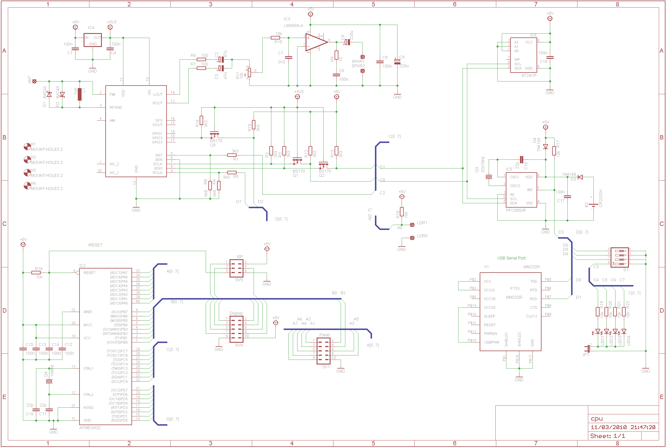
The last card contains all of the remaining circuits:
- AVR - mega664p (a large microcontroller but I have one spare) clocked at 20 MHz
- PCF8583 clock chip with battery back up and spare NVRAM
- LDR connectioned to an analogue input
- Switches (4) for setting options
- LEDs (4) for testing, debugging and finally error reporting
- USB-serial convertor
- Spare serial eeprom - unused
- Bidirectional 5V - 3.3V convertors
- Radio module
- Audio amplifier (LM386-4)
Eagle schematic and layout
Right click and "view image" or "save image as" to look at this schematic in full. The Eagle files are in the download section below.

Case design and final construction
I often find the case design a final finishing the hardest part of any project. What is suitable for the workshop does not necessarily obtain approval when it is brought into the house. Careful enquiries suggested that a jet black clock would be approved for the bedroom
