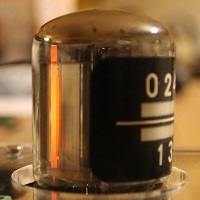
An E1T Tube Tester
Introduction
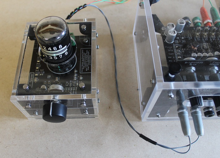
Over a period of some years I bought a number of E1T decade scaler tubes with the intent of making six of them into a clock. I decided to test them and started looking for the correct voltages, pulses and so on to experiment around. This quickly lead me to Ronald Dekker's tester and clock design.
This is the E1T Tube Tester designed by Ron Dekker. His web page also describes how this fascinating tube works as well. Therefore, I'm not going to deal with that but crack on with the construction of Ron's design which I offer as a kit. In a lot of respects I was left with very little to do - all the heavy lifting has been done for me. But… if you are going to use one of these amazing tubes then you must first read about its development.
This page and its documentation describes my version of the E1T Tester. It is (almost) fully open design all released under a Creative Commons ShareAlike 4.0 International license.
So you can roll your own entirely or you can buy a complete kit or or a minimal kit or a fully assembled tester - all described below or in the documentation.
Quick Links
Tester Powered Up
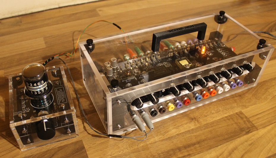
Using the E1T tester with the Sgitheach CRT Tester you configure the tester as follows:
- Heater configured for 6.3V operation
- HT configured for 300V operation
- Flyback enabled
- PDA multiplier disabled
- Cathode voltage, Focus voltage and PDA voltage selection jumper wires all removed. It is particularly important that the cathode voltage selection jumper is removed
The E1T tester is plugged into the CRT tester jacks as follows (assuming you are using the CRT Tester case):
- The two grey plugs are plugged into the grey heater output jacks on the front panel
- The orange jack is plugged into the orange 12V DC out jack on the back panel and its partner green jack plugged into the adjacent green ground jack
- The red jack is plugged into the 300V output jack on the back panel and its partner green jack plugged into the adjacent green ground jack
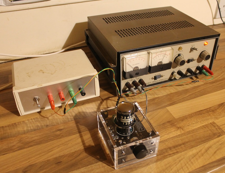
It is not necessary to use the CRT Tester as the power supply. Any power supplies that deliver 6.3V AC for the tube heater, 300V HT supply and 12 - 15V DC supply are likely to be entirely suitable. Here is the E1T tester being operated by a small 15V DC power supply and my trusty Heathkit IP17 PSU set to provide 300V DC HT and 6.3V AC for the heater.
Quick LinksDocumentation

The design is open source hardware.
You should look in the "/ E1T Projects / E1T Tester / " folder.
Here will also find the Eagle 7.7.0 schematics and board layouts, the PCB Gerbers, the STL files for 3D printed parts and DXF files for the laser cut acrylic.
Quick LinksKit Availability and Prices
The electronics kit is available in two forms:
Minimal Electronics Kit
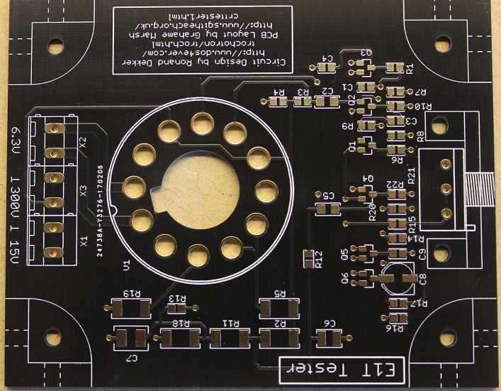
This is the bare PCB only. You will have to buy all the remaining components. I bought them from Farnell (Element14), Digikey, Ask Jan First and a few parts from Ebay. If you are going down this route then I assume you know what you are doing…
Price: £7.50 plus postage and insurance
Complete Electronics Kit

This is the kit when assembled (you get it in pieces!) with all the SMD parts fitted and all the through hole components and the complete case kit (laser cut 5mm thick clear acrylic, 3D printed parts, nuts, bolts, wire, pin receptacles, banana plugs … everything).
Price: £60 plus postage
I have been asked for a kit with the SMD parts unfitted. I have found that it is far quicker to solder paste a board, pick and place all the SMD parts then pop it in a reflow (toaster) oven, than it is to pick the SMD parts and put them all in bags. It also uses less resources as I'm not printing labels and using polythene or anti-static bags. So to say the least I am reluctant to supply a SMD unfitted kit.
Built and Tested
I am also willing to completely build and test the E1T tester - please contact me for a cost.
Quick LinksContact
Please contact me with any questions or enquires about ordering or postage.
Quick Links